
Solar-Powered Bottle-Weight Activated Phone Charging Station
View and Edit Project In Cirkit Designer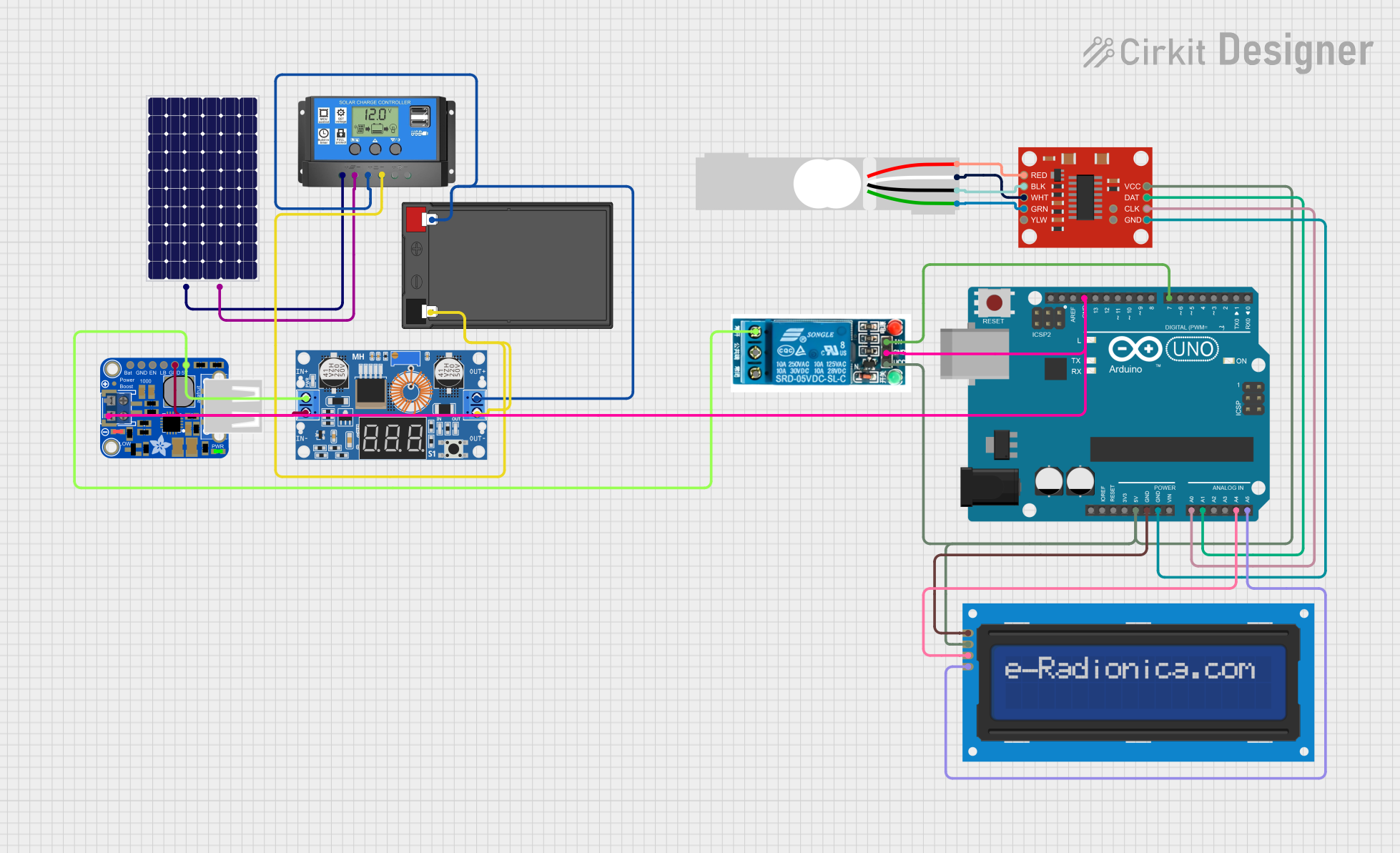
Solar Powered Charging Station Circuit Documentation
Summary
The Solar Powered Charging Station is an environmentally friendly solution that utilizes solar energy to charge electronic devices. The system is designed to activate a charging session when a bottle is placed on a load cell, indicating recycling participation. The charging session lasts for 5 minutes. The circuit comprises a solar panel, battery, charge controller, voltage regulator, load cell with an amplifier, an Arduino UNO microcontroller, an LCD screen for user interface, a relay to control the power to the charging circuit, and a PowerBoost module for stable 5V output.
Component List
Solar Panel
- Description: Converts sunlight into electrical energy.
- Pins:
+,-
12v 7ah Battery
- Description: Stores electrical energy for later use.
- Pins:
12v +,12v -
Solar Charge Controller
- Description: Manages the power going into the battery bank from the solar array.
- Pins:
Solar Cell +,Solar Cell -,Battery +,Battery -,Load +,Load -
XL4015 5A DC Buck Step-down Converter
- Description: Steps down voltage to a lower level.
- Pins:
Output +,Output -,Input +,Input -
SparkFun Load Cell Amplifier - HX711
- Description: Amplifies the signal from the load cell.
- Pins:
GND,CLK,DAT,VCC,YLW,GRN,WHT,BLK,RED,B-,B+
LCD screen 16x2 I2C
- Description: Displays information to the user.
- Pins:
SCL,SDA,VCC,GND
PowerBoost 1000 Basic Terminal USB
- Description: Provides a 5V output from battery power.
- Pins:
VBAT,GND,ENABLE,LBO,5.0V
Load Cell - Red/white/black/green
- Description: Measures the weight of the bottle placed on it.
- Pins:
E+,A-,E-,A+
Arduino UNO
- Description: The main microcontroller board that controls the system.
- Pins:
UNUSED,IOREF,Reset,3.3V,5V,GND,Vin,A0toA5,SCL,SDA,AREF,D13toD0
5v Relay
- Description: Electrically operated switch to control the charging circuit.
- Pins:
Normally Open,Common terminal,Normally Closed,In,GND,VCC
Wiring Details
Solar Panel
+connected to Solar Charge ControllerSolar Cell +-connected to Solar Charge ControllerSolar Cell -
12v 7ah Battery
12v +connected to Solar Charge ControllerBattery +and XL4015Output +12v -connected to Solar Charge ControllerBattery -and XL4015Output -
Solar Charge Controller
Load +not detailed in the provided net list.Load -not detailed in the provided net list.
XL4015 5A DC Buck Step-down Converter
Input +connected to 5v RelayNormally Openand PowerBoost5.0VInput -connected to PowerBoostGND
SparkFun Load Cell Amplifier - HX711
GNDconnected to Arduino UNOGNDCLKconnected to Arduino UNOA0DATconnected to Arduino UNOA1VCCconnected to 5v RelayVCC, Arduino UNO5V, and LCD screenVCCYLW,GRN,WHT,BLK,RED,B-,B+connected to corresponding Load Cell pins.
LCD screen 16x2 I2C
SCLconnected to Arduino UNOA5SDAconnected to Arduino UNOA4VCCconnected to Arduino UNO5VGNDconnected to Arduino UNOGND
PowerBoost 1000 Basic Terminal USB
5.0Vconnected to 5v RelayNormally Openand XL4015Input +GNDconnected to XL4015Input -, 5v RelayGND, and Arduino UNOGND
Load Cell - Red/white/black/green
A+connected to HX711GRNA-connected to HX711WHTE-connected to HX711BLKE+connected to HX711RED
Arduino UNO
GNDconnected to HX711GND, LCD screenGND, PowerBoostGND, and 5v RelayGNDA0connected to HX711CLKA1connected to HX711DATA4connected to LCD screenSDAA5connected to LCD screenSCL5Vconnected to HX711VCC, LCD screenVCC, and 5v RelayVCCD7connected to 5v RelayIn
5v Relay
Normally Openconnected to XL4015Input +and PowerBoost5.0VCommon terminalnot detailed in the provided net list.Normally Closednot detailed in the provided net list.Inconnected to Arduino UNOD7GNDconnected to PowerBoostGNDand Arduino UNOGNDVCCconnected to HX711VCCand Arduino UNO5V
Documented Code
/*
 * Solar Powered Charging Station
 * This Arduino sketch controls a solar-powered charging station. When a bottle
 * is placed on the load cell, the system grants 5 minutes of phone charging
 * time. The system uses an LCD to display status messages and a relay to
 * control the charging circuit.
 */

#include <Wire.h>
#include <LiquidCrystal_I2C.h>

// Pin definitions
const int loadCellDataPin = A1;
const int loadCellClockPin = A0;
const int relayPin = 7;

// Load cell calibration factor
const float calibrationFactor = -7050.0;

// LCD setup
LiquidCrystal_I2C lcd(0x27, 16, 2);

void setup() {
  // Initialize serial communication
  Serial.begin(9600);

  // Initialize LCD
  lcd.begin();
  lcd.backlight();
  lcd.setCursor(0, 0);
  lcd.print("Charging Station");

  // Initialize relay pin
  pinMode(relayPin, OUTPUT);
  digitalWrite(relayPin, LOW);

  // Initialize load cell
  scale.begin(loadCellDataPin, loadCellClockPin);
  scale.set_scale(calibrationFactor);
  scale.tare();
}

void loop() {
  // Read load cell value
  float weight = scale.get_units(10);

  // Check if a bottle is placed
  if (weight > 50) { // Adjust threshold as needed
    lcd.setCursor(0, 1);
    lcd.print("Charging...");
    digitalWrite(relayPin, HIGH);
    delay(300000); // 5 minutes
    digitalWrite(relayPin, LOW);
    lcd.setCursor(0, 1);
    lcd.print("Done");
    delay(2000);
    lcd.setCursor(0, 1);
    lcd.print("                ");
  }
  delay(1000);
}
This code is responsible for controlling the charging station. It reads the weight from the load cell and, if the weight exceeds a certain threshold, it activates the relay to allow charging. The LCD screen displays the status of the charging session. The code includes setup for the load cell, LCD, and relay, as well as the main loop that checks the load cell and controls the relay.