Arduino Nano-Based Drowsiness Detector with IR Sensor, Buzzer, Vibration Motor, and RF Communication
Circuit Documentation
Summary
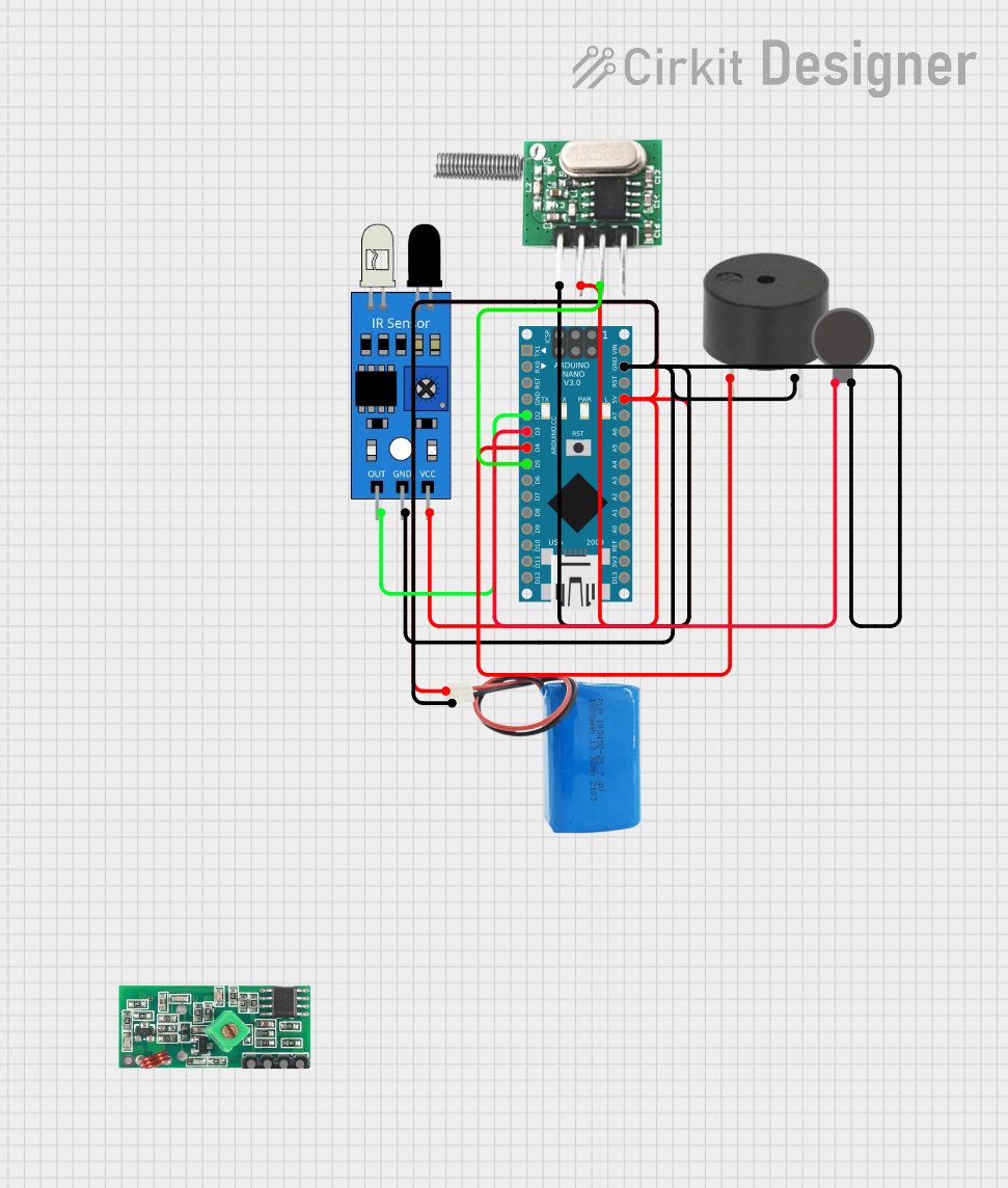
This circuit is designed to interface an Arduino Nano with an IR sensor, a buzzer, a vibration motor, and an RF 433 MHz transmitter module. The purpose of the circuit is to detect an event via the IR sensor and respond by activating the buzzer and vibration motor, as well as transmitting an alert signal through the RF transmitter. The circuit is powered by a 5V battery.
Component List
Arduino Nano
- Microcontroller board based on the ATmega328P
- It has a variety of digital and analog I/O pins.
IR Sensor
- An infrared sensor capable of detecting IR signals, commonly used for proximity or motion detection.
Buzzer
- An electromechanical component that produces sound when energized.
Vibration Motor
- A small motor that vibrates when electricity is applied, used for haptic feedback.
RF 433 MHz Transmitter
- A wireless communication module that operates at 433 MHz for transmitting data.
433 MHz RF Receiver Module
- A wireless communication module that operates at 433 MHz for receiving data.
5V Battery
- A power source that provides 5 volts to power the circuit.
Wiring Details
Arduino Nano
- D2 connected to IR Sensor (out)
- D3 connected to Vibration Motor (+)
- D4 connected to Buzzer (PIN)
- D5 connected to RF 433 MHz Transmitter (Data)
- GND connected to common ground net
- 5V connected to common power net
IR Sensor
- Out connected to Arduino Nano (D2)
- GND connected to common ground net
- VCC connected to common power net
Buzzer
- PIN connected to Arduino Nano (D4)
- GND connected to common ground net
Vibration Motor
- connected to Arduino Nano (D3)
- connected to common ground net
RF 433 MHz Transmitter
- Data connected to Arduino Nano (D5)
- -ve connected to common ground net
- +ve connected to common power net
5V Battery
- Positive connected to common power net
- Negative connected to common ground net
Documented Code
#include <VirtualWire.h>

const int irSensorPin = 2;
const int buzzerPin = 3; // PWM-capable pin
const int vibratorPin = 4;
const int rfTxPin = 5;

void setup() {
  pinMode(irSensorPin, INPUT);
  pinMode(buzzerPin, OUTPUT);
  pinMode(vibratorPin, OUTPUT);

  // Initialize RF Transmitter
  vw_set_tx_pin(rfTxPin);
  vw_setup(2000); // Bits per second

  Serial.begin(9600);
}

void loop() {
  int irValue = digitalRead(irSensorPin);

  if (irValue == LOW) { // Assuming LOW indicates eye closure or head movement
    tone(buzzerPin, 1000); // Generate a 1kHz tone on the buzzer
    digitalWrite(vibratorPin, HIGH); // Activate vibrator

    // Send RF signal
    const char *msg = "Alert";
    vw_send((uint8_t *)msg, strlen(msg));
    vw_wait_tx(); // Wait until the message is sent

    delay(1000); // Keep buzzer and vibrator on for 1 second

    noTone(buzzerPin); // Deactivate buzzer
    digitalWrite(vibratorPin, LOW); // Deactivate vibrator
  }

  delay(100); // Small delay to avoid rapid triggering
}
The code is written for the Arduino Nano and utilizes the VirtualWire library for RF communication. The IR sensor is read on pin D2, and when a LOW signal is detected, indicating an event, the buzzer is activated on pin D3, the vibration motor on pin D4, and an "Alert" message is transmitted via the RF transmitter on pin D5. The buzzer and vibrator are activated for 1 second before being turned off. A short delay is included in the loop to prevent rapid re-triggering of the alert.