Cirkit Designer
Your all-in-one circuit design IDE
Home /
Project Documentation
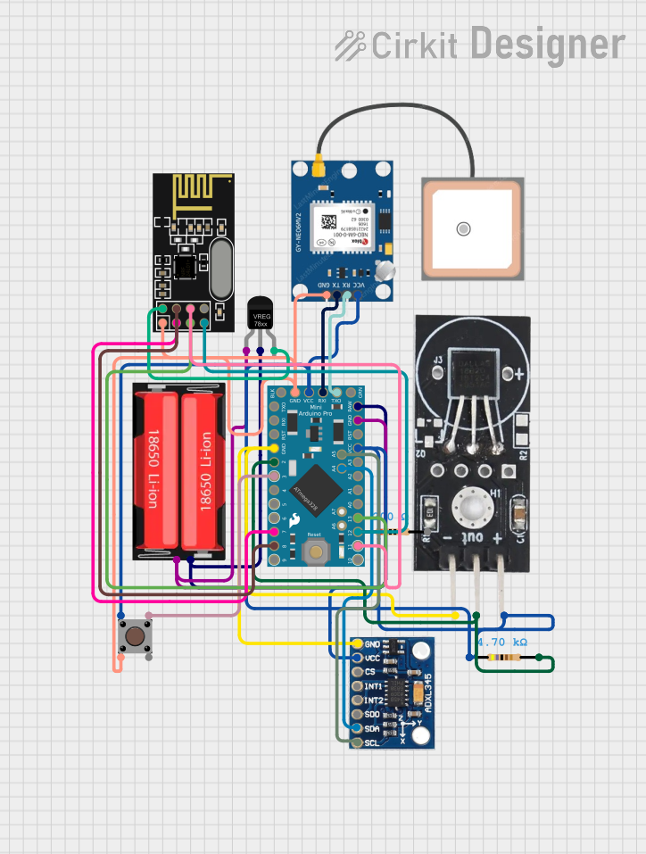
Arduino Pro Mini Based GPS and Temperature Tracking System with NRF24L01 Wireless Communication

Circuit Documentation
Summary
This document provides a detailed overview of a circuit that includes an Arduino Pro Mini as the central microcontroller, interfaced with various sensors and modules including a DS18B20 Temperature Sensor, GPS NEO 6M module, ADXL345 accelerometer, NRF24L01 wireless communication module, and a voltage regulator. The circuit is powered by an 18650 Li-Ion battery and includes a pushbutton and resistors for input and signal conditioning.
Component List
Arduino Pro Mini
- Microcontroller board based on the ATmega328
- Operating Voltage: 3.3V or 5V (depending on the model)
- Digital I/O Pins: 14 (of which 6 provide PWM output)
- Analog Input Pins: 8
- Clock Speed: 8 MHz or 16 MHz
DS18B20 Temperature Sensor
- Programmable resolution temperature sensor
- Operating Voltage: 3.0V to 5.5V
- Output: Digital signal via a one-wire bus
GPS NEO 6M
- GPS module with ceramic antenna
- Operating Voltage: 3.3V to 5V
- Communication: Serial (TX/RX)
ADXL345
- 3-axis accelerometer with high resolution (13-bit)
- Operating Voltage: 2.0V to 3.6V
- Communication: I2C/SPI
NRF24L01
- 2.4GHz wireless transceiver module
- Operating Voltage: 1.9V to 3.6V
- Communication: SPI
Voltage Regulator
- Regulates input voltage to a stable output voltage
- Input Voltage (IN): Typically higher than the output
- Output Voltage (OUT): Regulated voltage
Pushbutton
- Momentary pushbutton switch
- Typically used as a user input device
Resistor (200 Ohms)
- Resistance: 200 Ohms
- Used for current limiting or voltage division
Resistor (4700 Ohms)
- Resistance: 4700 Ohms
- Used for current limiting or voltage division
18650 Li-Ion Battery
- Rechargeable battery
- Nominal Voltage: 3.7V
Wiring Details
Arduino Pro Mini
TXOconnected to GPS NEO 6MRXRXIconnected to GPS NEO 6MTXVCCconnected to GPS NEO 6MVCC, ADXL345VCC, PushbuttonPin 1 (in), DS18B20VCC, and Resistor (4700 Ohms)pin1GNDconnected to NRF24L01GND, GPS NEO 6MGND, PushbuttonPin 2 (in), ADXL345GND, and DS18B20GNDA4connected to ADXL345SDAA5connected to ADXL345SCLRAWconnected to 18650 Li-Ion BatteryPositivethrough Voltage RegulatorIND3connected to PushbuttonPin 3 (out)D2connected to DS18B20OUTthrough Resistor (4700 Ohms)pin2SCK,MISO,MOSIconnected to NRF24L01SCK,MISO,MOSIrespectivelyD8connected to NRF24L01CSND7connected to NRF24L01CE
DS18B20 Temperature Sensor
GNDconnected to common groundVCCconnected to common VCCOUTconnected to Arduino Pro MiniD2through Resistor (4700 Ohms)
GPS NEO 6M
RXconnected to Arduino Pro MiniTXOTXconnected to Arduino Pro MiniRXIVCCconnected to common VCCGNDconnected to common ground
ADXL345
GNDconnected to common groundVCCconnected to common VCCSDAconnected to Arduino Pro MiniA4SCLconnected to Arduino Pro MiniA5
NRF24L01
GNDconnected to common groundVCC (3V)connected to Voltage RegulatorOUTCEconnected to Arduino Pro MiniD7CSNconnected to Arduino Pro MiniD8SCKconnected to Arduino Pro MiniSCKMISOconnected to Arduino Pro MiniMISOMOSIconnected to Arduino Pro MiniMOSI
Voltage Regulator
GNDconnected to common ground and 18650 Li-Ion BatteryNegativeINconnected to 18650 Li-Ion BatteryPositiveOUTconnected to NRF24L01VCC (3V)
Pushbutton
Pin 1 (in)connected to common VCCPin 2 (in)connected to common groundPin 3 (out)connected to Arduino Pro MiniD3
Resistor (200 Ohms)
- Not explicitly connected in the provided net list.
Resistor (4700 Ohms)
pin1connected to common VCCpin2connected to Arduino Pro MiniD2and DS18B20OUT
18650 Li-Ion Battery
Positiveconnected to Voltage RegulatorINand Arduino Pro MiniRAWNegativeconnected to common ground
Documented Code
Arduino Pro Mini (sketch.ino)
void setup() {
  // put your setup code here, to run once:

}

void loop() {
  // put your main code here, to run repeatedly:

}
Additional Notes
- The provided code is a template and does not include any functionality. It needs to be populated with the initialization and operational code for the sensors and modules connected to the Arduino Pro Mini.
- The
documentation.txtfile is empty and does not contain any additional information.