
ESP32-Based Sensor Monitoring and Notification System with Servo Control
View and Edit Project In Cirkit Designer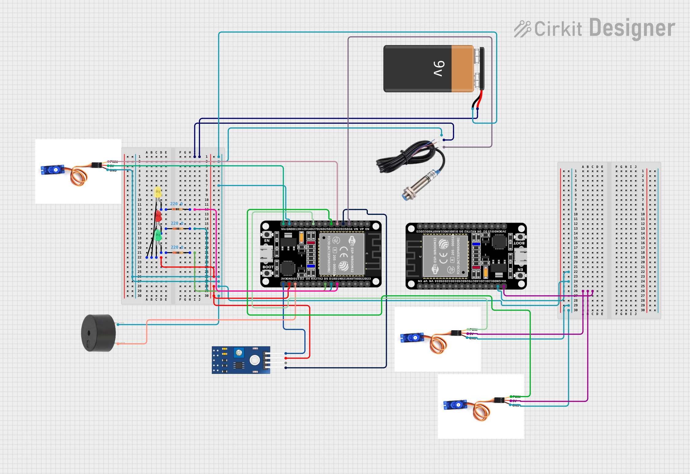
Circuit Documentation
Summary
This circuit integrates various components controlled by an ESP32 microcontroller to perform a set of functions. The circuit includes inductive and IR sensors for input, LEDs and a buzzer for output, and servo motors for actuation. A 9V battery provides power to the system. The ESP32 reads sensor inputs and controls the outputs accordingly. The circuit is designed to be modular, with each component connected to the ESP32, allowing for easy modifications or expansions.
Component List
Microcontroller
- ESP32 (30 pin): A powerful microcontroller with Wi-Fi and Bluetooth capabilities. It has a variety of digital and analog I/O pins.
Sensors
- Inductive Sensor: Detects metallic objects within close proximity without direct contact.
- TCRT 5000 IR Sensor: An infrared sensor used for line tracking or obstacle detection based on reflectivity.
Actuators
- SG90 Servo Motor: A small and lightweight servo motor capable of precise angular positioning.
Power Supply
- 9V Battery: Provides the necessary power to the circuit.
Output Devices
- Buzzer: An audible signaling device that can be used for alerts or notifications.
- LED (Green, Yellow, Red): Light Emitting Diodes used as visual indicators.
Passive Components
- Resistor (220 Ohms): Limits current to protect components such as LEDs from excessive current.
Wiring Details
ESP32 (30 pin)
- EN, VP, VN, D34-D27, D14-D12, D13, TX0, RX0, D21-D19, D18, D5, TX2, RX2, D4, D2, D15, 3V3: Various I/O pins used for interfacing with sensors, actuators, and other components.
- GND: Connected to the ground plane of the circuit.
- Vin: Power input connected to the 9V battery.
Inductive Sensor
- Signal: Connected to the ESP32 for signal output.
- VCC: Power input connected to the 9V battery.
- GND: Connected to the ground plane of the circuit.
TCRT 5000 IR Sensor
- VCC: Powered by the 3.3V output from the ESP32.
- GND: Connected to the ground plane of the circuit.
- DO: Digital output (not used in this circuit).
- AO: Analog output connected to the ESP32.
SG90 Servo Motor
- PWM: Pulse Width Modulation input controlled by the ESP32.
- 5V: Power input connected to the Vin of the ESP32.
- GND: Connected to the ground plane of the circuit.
9V Battery
- +: Positive terminal connected to the VCC of the inductive sensor and Vin of the ESP32.
- -: Negative terminal connected to the ground plane of the circuit.
Buzzer
- PIN: Control pin connected to the ESP32.
- GND: Connected to the ground plane of the circuit.
LED (Green, Yellow, Red)
- Cathode: Connected to the ground plane of the circuit.
- Anode: Connected to the ESP32 through a 220 Ohm resistor.
Resistor (220 Ohms)
- Pin1: Connected to the anode of an LED.
- Pin2: Connected to an I/O pin of the ESP32.
Documented Code
No code was provided for the microcontrollers in the circuit. The expected code would typically initialize the I/O pins, read sensor inputs, control the actuators, and manage the output devices based on the logic defined for the circuit's operation.