Cirkit Designer
Your all-in-one circuit design IDE
Home /
Project Documentation
Audio Signal Routing with TRRS 3.5mm Jack Breakouts

Circuit Documentation
Summary of the Circuit
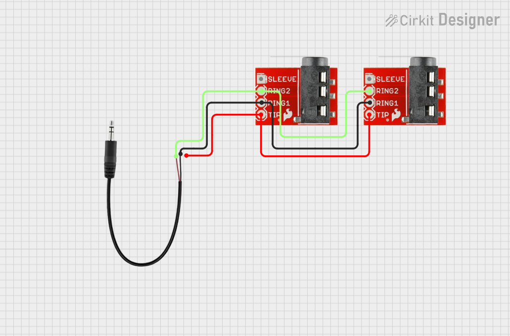
This circuit consists of two TRRS 3.5mm Jack Breakouts and one 3.5mm Audio Jack with 3 pins. The circuit is designed to interconnect audio signals between the TRRS jack breakouts and the 3.5mm audio jack. The TRRS jack breakouts are used to interface with TRRS-type connectors, which are common in audio equipment such as headphones and microphones. The 3.5mm Audio Jack is a standard connector for stereo audio signals.
Component List
TRRS 3.5mm Jack Breakout
- Pins: Sleeve, Ring2, Ring1, Tip
- Description: A breakout board for a TRRS 3.5mm jack that allows access to all four connections: sleeve, ring2, ring1, and tip.
3.5mm Audio Jack 3 Pin
- Pins: L (Left Audio), R (Right Audio), GND (Ground)
- Description: A standard 3-pin 3.5mm audio jack for stereo audio signals with connections for left audio, right audio, and ground.
Wiring Details
TRRS 3.5mm Jack Breakout
- Ring2 is connected to the L (Left Audio) pin of the 3.5mm Audio Jack 3 Pin.
- Tip is connected to the R (Right Audio) pin of the 3.5mm Audio Jack 3 Pin.
- Ring1 is connected to the GND (Ground) pin of the 3.5mm Audio Jack 3 Pin.
3.5mm Audio Jack 3 Pin
- L (Left Audio) is connected to the Ring2 pin of both TRRS 3.5mm Jack Breakouts.
- R (Right Audio) is connected to the Tip pin of both TRRS 3.5mm Jack Breakouts.
- GND (Ground) is connected to the Ring1 pin of both TRRS 3.5mm Jack Breakouts.
Documented Code
Microcontroller Code (sketch.ino)
void setup() {
  // put your setup code here, to run once:

}

void loop() {
  // put your main code here, to run repeatedly:

}
Additional Documentation (documentation.txt)
No additional code documentation was provided.
Note: The provided code does not interact with the audio components directly and appears to be a template with no specific functionality. Additional code may be required to perform tasks such as audio signal processing or control.