Arduino-Controlled Line-Following Robot with Dual IR Sensors and L298N Motor Driver
Circuit Documentation
Summary
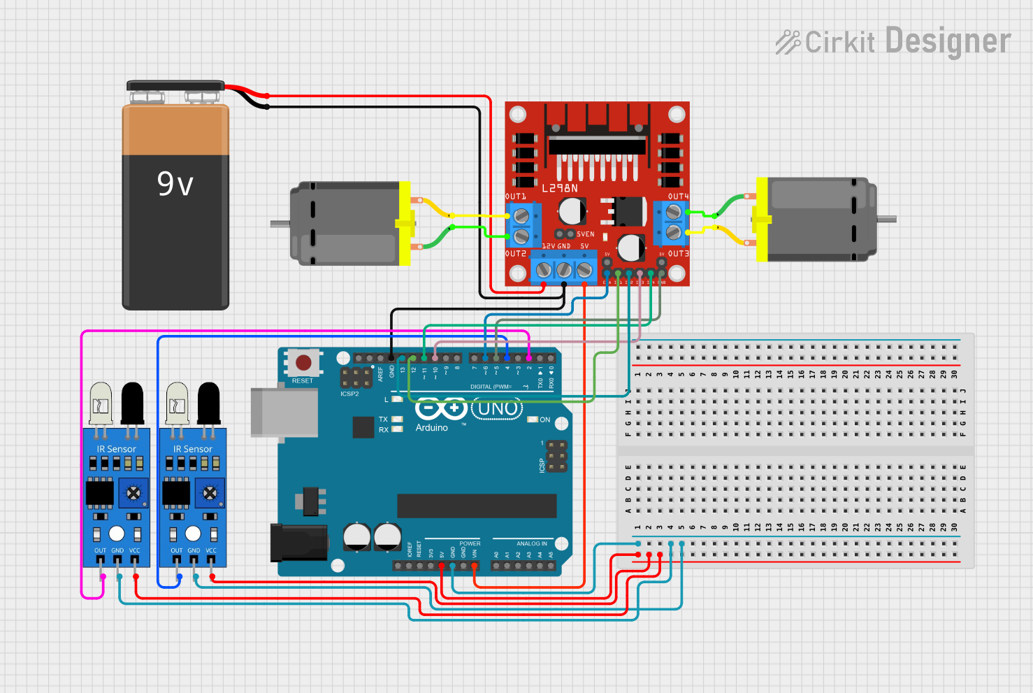
The circuit in question is designed to control a pair of DC motors using an Arduino UNO microcontroller and an L298N DC motor driver. The system also includes two infrared sensors for detecting track lines, which are used to guide the motors' actions. A 9V battery provides the power source for the motor driver and indirectly for the Arduino through voltage regulation.
Component List
Arduino UNO
- Microcontroller board based on the ATmega328P
- It has 14 digital input/output pins, 6 analog inputs, a 16 MHz quartz crystal, a USB connection, a power jack, an ICSP header, and a reset button.
9V Battery
- Standard 9V battery used to provide power to the circuit.
DC Motor (x2)
- Electric motor that runs on direct current (DC) electricity.
- Used for creating rotational motion in the system.
L298N DC Motor Driver
- A motor driver module capable of driving two DC motors or one stepper motor.
- It has two H-bridges and can handle a substantial current.
IR Sensor (x2)
- Infrared sensors used for line tracking.
- Each sensor has an output that goes high or low depending on the presence of a line.
Wiring Details
Arduino UNO
5Vpin provides power to both IR sensors.GNDpin is connected to the ground of the IR sensors, L298N motor driver, and the negative terminal of the 9V battery.Vinpin is connected to the5Vpin of the L298N motor driver.- Digital pins
D13,D12,D11,D10,D6, andD5are connected to theIN2,IN1,IN4,IN3,ENA, andENBpins of the L298N motor driver, respectively. - Digital pins
D4andD2are connected to the output of the IR sensors.
9V Battery
+terminal is connected to the12Vpin of the L298N motor driver.-terminal is connected to the ground of the circuit.
DC Motor #1
pin 1is connected toOUT2of the L298N motor driver.pin 2is connected toOUT1of the L298N motor driver.
DC Motor #2
pin 1is connected toOUT4of the L298N motor driver.pin 2is connected toOUT3of the L298N motor driver.
L298N DC Motor Driver
OUT1,OUT2,OUT3, andOUT4are connected to the respective pins of the DC motors.12Vpin is connected to the positive terminal of the 9V battery.GNDpin is connected to the ground of the circuit.5Vpin is connected to theVinpin of the Arduino UNO.ENA,IN1,IN2,IN3,IN4, andENBare connected to the respective pins of the Arduino UNO.
IR Sensor #1
outpin is connected toD4on the Arduino UNO.gndpin is connected to the ground of the circuit.vccpin is connected to5Von the Arduino UNO.
IR Sensor #2
outpin is connected toD2on the Arduino UNO.gndpin is connected to the ground of the circuit.vccpin is connected to5Von the Arduino UNO.
Documented Code
// Definition of pins for motor speed control
// Activates ENA (enable a) and ENB (enable b)
int velmotor1 = 6;
int velmotor2 = 5;

// Definition of motor control pins In1, In2, In3, In4
int motor1A = 13;
int motor1B = 12;
int motor2C = 11;
int motor2D = 10;

// Infrared sensors - left and right
// Will detect the track to activate functions
int infrapinr = 2;
int infrapinl = 4;

// Variable to capture the values - 0 for light ground and 1 for dark ground
int valorinfrar = 0;
int valorinfral = 0;

// Initial configuration
void setup() {
  Serial.begin(9600);
  delay(1000);
  // Set the mode of the infrared sensor pins
  pinMode(infrapinr, INPUT);
  pinMode(infrapinl, INPUT);

  // Set the mode of the motor control pins
  pinMode(motor1A, OUTPUT);
  pinMode(motor1B, OUTPUT);
  pinMode(motor2C, OUTPUT);
  pinMode(motor2D, OUTPUT);
  pinMode(velmotor1, OUTPUT);
  pinMode(velmotor2, OUTPUT);

  // Set the motor speed between 150/255
  analogWrite(velmotor1, 150);
  analogWrite(velmotor2, 150);

  // Configure the direction of rotation
  digitalWrite(motor1A, LOW);
  digitalWrite(motor1B, LOW);
  digitalWrite(motor2C, LOW);
  digitalWrite(motor2D, LOW);
}

void loop() {
  // Read the values of the infrared sensors - 0 for light ground and 1 for dark ground
  valorinfrar = digitalRead(infrapinr);
  valorinfral = digitalRead(infrapinl);
  Serial.println(valorinfrar);
  Serial.println(valorinfral);

  // Four scenarios
  // Straight ahead
  if (valorinfrar == 0 & valorinfral == 0) {
    Serial.println("none on line");
    digitalWrite(motor1A, HIGH);
    digitalWrite(motor2D, HIGH);
    delay(20);

    digitalWrite(motor1A, LOW);
    digitalWrite(motor2D, LOW);
    delay(20);
  }
  // Line found on the right side
  if (valorinfrar == 1 & valorinfral == 0) {
    Serial.println("right on line");
    digitalWrite(motor1A, LOW);
    digitalWrite(motor2D, LOW);
    delay(25);

    digitalWrite(motor1A, HIGH);
    digitalWrite(motor2D, LOW);
    delay(20);
  }
  // Line found on the left side
  if (valorinfrar == 0 & valorinfral == 1) {
    Serial.println("left on line");
    digitalWrite(motor1A, LOW);
    digitalWrite(motor2D, LOW);
    delay(25);

    digitalWrite(motor1A, LOW);
    digitalWrite(motor2D, HIGH);
    delay(20);
  }
  // Line found on both sides
  if (valorinfrar == 1 & valorinfral == 1) {
    Serial.println("both on line");
    // Stop the motors
    digitalWrite(motor1A, LOW);
    digitalWrite(motor1B, LOW);
    digitalWrite(motor2C, LOW);
    digitalWrite(motor2D, LOW);
  }
}
This code is responsible for reading the infrared sensors and controlling the motors based on the sensor readings. It sets up the motor control pins and the infrared sensor pins, defines the initial motor speed, and then enters a loop where it reads the sensor values and controls the motors accordingly. The comments within the code provide additional context for each section and operation.