Cirkit Designer
Your all-in-one circuit design IDE
Home /
Project Documentation
ESP32-Based Luminosity Sensor with Serial Output
Circuit Documentation
Summary of the Circuit
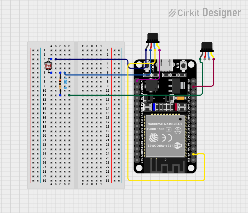
This circuit consists of a photocell (LDR) connected to an ESP32 microcontroller through a voltage divider configuration with a resistor. The ESP32 reads the analog value from the LDR to measure light intensity. The circuit also includes Qwiic cables for power distribution and potential I2C communication, although the I2C lines are not utilized in the current configuration.
Component List
Photocell (LDR)
- Description: A light-dependent resistor whose resistance varies with light intensity.
- Pins: pin 0, pin 1
Resistor
- Description: A passive two-terminal electrical component that implements electrical resistance as a circuit element.
- Resistance: 200 Ohms
- Pins: pin1, pin2
Qwiic Cable - Breadboard Jumper (4-pin)
- Description: A 4-pin cable used for making quick and easy prototyping connections, including power (GND, 3.3V) and I2C communication (SDA, SCL).
- Pins: GND, 3.3V, SDA, SCL
ESP32 (30 pin)
- Description: A microcontroller with Wi-Fi and Bluetooth capabilities, featuring a variety of GPIO pins for interfacing with peripherals.
- Pins: EN, VP, VN, D34, D35, D32, D33, D25, D26, D27, D14, D12, D13, GND, Vin, D23, D22, TX0, RX0, D21, D19, D18, D5, TX2, RX2, D4, D2, D15, 3V3
Wiring Details
Photocell (LDR)
- pin 0: Connected to the 3.3V power supply through a resistor.
- pin 1: Connected to GND.
Resistor
- pin1: Connected to pin 0 of the Photocell (LDR).
- pin2: Connected to GND.
Qwiic Cable - Breadboard Jumper (4-pin)
- GND: Connected to pin 1 of the Photocell (LDR) and pin2 of the Resistor.
- 3.3V: Connected to pin 0 of the Photocell (LDR).
- SDA: Connected to VP pin of the ESP32.
- SCL: Connected to 3V3 pin of the ESP32 and GND of the ESP32.
ESP32 (30 pin)
- VP: Connected to SDA of the Qwiic Cable.
- 3V3: Connected to SCL of the Qwiic Cable.
- GND: Connected to SCL of another Qwiic Cable.
Documented Code
// Code for ESP32 microcontroller
const int LDR_PIN = 34; // Change to your chosen pin

void setup() {
  Serial.begin(115200); // Start serial communication at 115200 baud
}

void loop() {
  int ldrValue = analogRead(LDR_PIN); // Read the value from the LDR
  Serial.print("LDR Value: ");
  Serial.println(ldrValue); // Print the LDR value to the Serial Monitor

  delay(1000); // Wait for a second before the next reading
}
Filename: sketch.ino
Description: This code is written for the ESP32 microcontroller to read the analog value from an LDR connected to pin 34. The value is then printed to the Serial Monitor every second.