
Arduino UNO Controlled IR Sensor with 7-Segment Display Indicator
View and Edit Project In Cirkit Designer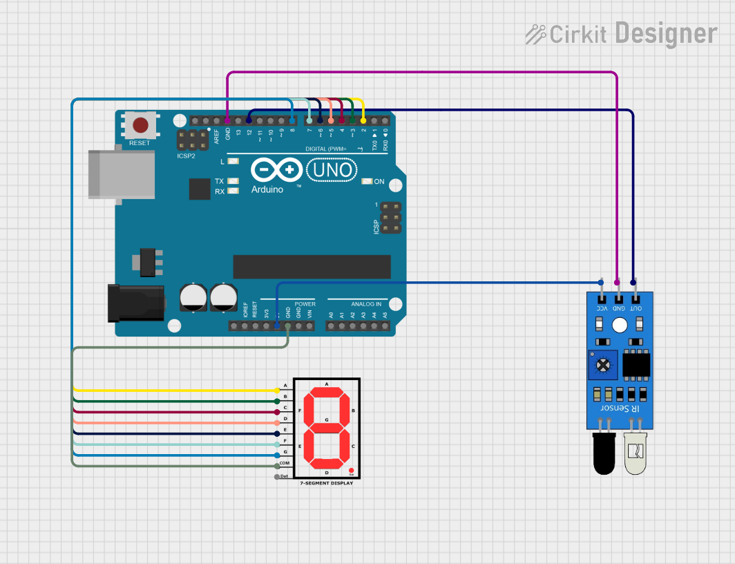
Circuit Documentation
Summary of the Circuit
This circuit consists of an Arduino UNO microcontroller, an infrared (IR) sensor, and a 7-segment display. The Arduino UNO is used as the central processing unit to control the behavior of the 7-segment display based on the input from the IR sensor. The IR sensor detects the presence of an object or motion and sends a signal to the Arduino, which then updates the display accordingly. The 7-segment display shows numerical patterns based on the signal received from the IR sensor.
Component List
Arduino UNO
- Description: A microcontroller board based on the ATmega328P.
- Purpose: Acts as the central processing unit for the circuit, reading sensor inputs and controlling the 7-segment display.
IR Sensor
- Description: A sensor that detects infrared light, commonly used for proximity or motion detection.
- Purpose: Provides input to the Arduino UNO when an object is detected.
7-Segment Display
- Description: An electronic display device for displaying decimal numerals.
- Purpose: Shows numerical patterns as directed by the Arduino UNO.
Wiring Details
Arduino UNO
- 5V connected to IR Sensor VCC
- GND connected to 7-Segment Display COM and IR Sensor GND
- D12 connected to IR Sensor OUT
- D2 - D8 connected to 7-Segment Display segments A-G respectively
IR Sensor
- VCC connected to Arduino UNO 5V
- GND connected to Arduino UNO GND
- OUT connected to Arduino UNO D12
7-Segment Display
- A - G connected to Arduino UNO D2 - D8 respectively
- COM connected to Arduino UNO GND
Documented Code
int aSegment = 2;
int bSegment = 3;
int cSegment = 4;
int dSegment = 5;
int eSegment = 6;
int fSegment = 7;
int gSegment = 8;
int time = 100;
int t = 0;

void setup() {
    for (int x = 2; x <= 8; x++) {
        pinMode(x, OUTPUT);
    }
    pinMode(12, INPUT);
}

void loop() {
    if (digitalRead(12) == LOW) {
        t++;
        delay(100);
    }
    switch (t) {
        case 0: pattern0(); break;
        case 1: pattern1(); break;
        case 2: pattern2(); break;
        case 3: pattern3(); break;
        case 4: pattern4(); break;
        case 5: pattern5(); break;
        case 6: pattern6(); break;
        case 7: pattern7(); break;
        case 8: pattern8(); break;
        case 9: pattern9(); break;
        case 10: pattern10(); break;
        default: t = 0; break;
    }
}

void pattern0() {
    digitalWrite(aSegment, HIGH);
    digitalWrite(bSegment, HIGH);
    digitalWrite(cSegment, HIGH);
    digitalWrite(dSegment, HIGH);
    digitalWrite(eSegment, HIGH);
    digitalWrite(fSegment, HIGH);
    digitalWrite(gSegment, LOW);
    delay(time);
}

// Additional patterns (pattern1 to pattern9) are defined similarly.

void pattern10() {
    digitalWrite(aSegment, LOW);
    digitalWrite(bSegment, LOW);
    digitalWrite(cSegment, LOW);
    digitalWrite(dSegment, LOW);
    digitalWrite(eSegment, LOW);
    digitalWrite(fSegment, LOW);
    digitalWrite(gSegment, LOW);
    delay(time);
    t = 0;
}
Note: The code provided includes functions for displaying patterns 0 through 9 on the 7-segment display. The pattern10 function resets the display and the pattern counter t. The IR sensor input is read on pin D12, and when detected, it increments the pattern counter t, which then selects the corresponding pattern function to display on the 7-segment display.