
Circuit Documentation
Summary
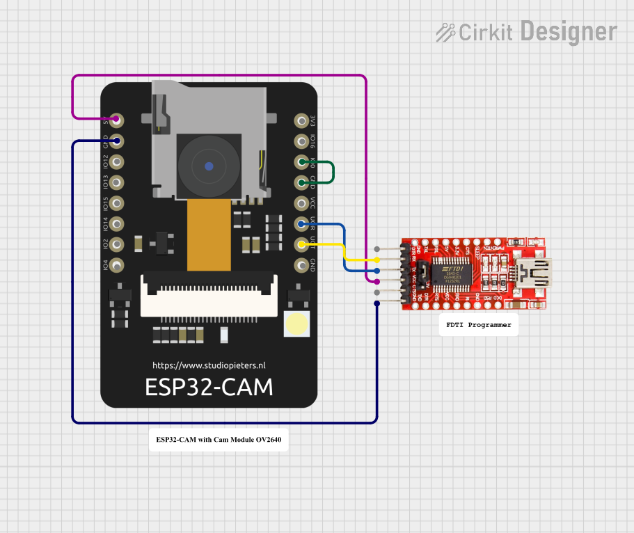
This circuit involves an ESP32 CAM module connected to an FTDI Programmer. The ESP32 CAM is used for capturing images and streaming video, while the FTDI Programmer is used for programming and providing power to the ESP32 CAM. The ESP32 CAM is programmed to connect to a WiFi network and serve a web page that streams video from the camera.
Component List
ESP32 CAM
- Description: A low-cost development board with a camera module, capable of capturing images and streaming video.
- Pins: 5V, GND, GPIO12, GPIO13, GPIO15, GPIO14, GPIO2, GPIO4, 3.3V, GPIO16, GPIO0, 3.3V / 5V / P_OUT, GPIO3 / RX, GPIO1 / TX
FTDI Programmer
- Description: A USB-to-serial adapter used for programming and providing power to the ESP32 CAM.
- Pins: DTR, RX, TX, VCC, CTS, GND
Comment
- Description: Placeholder for comments in the circuit design.
- Pins: None
Wiring Details
ESP32 CAM
- 5V: Connected to FTDI Programmer VCC
- GND: Connected to FTDI Programmer GND
- GPIO0: Connected to ESP32 CAM GND
- GPIO3 / RX: Connected to FTDI Programmer TX
- GPIO1 / TX: Connected to FTDI Programmer RX
FTDI Programmer
- VCC: Connected to ESP32 CAM 5V
- GND: Connected to ESP32 CAM GND
- TX: Connected to ESP32 CAM GPIO3 / RX
- RX: Connected to ESP32 CAM GPIO1 / TX
Code Documentation
ESP32 CAM Code
#include "src/OV2640.h"
#include <WiFi.h>
#include <WebServer.h>
#include <WiFiClient.h>

// Select camera model
//#define CAMERA_MODEL_WROVER_KIT
#define CAMERA_MODEL_ESP_EYE
//#define CAMERA_MODEL_M5STACK_PSRAM
//#define CAMERA_MODEL_M5STACK_WIDE
//#define CAMERA_MODEL_AI_THINKER

#include "camera_pins.h"

#define SSID1 "ssid"
#define PWD1 "password"

OV2640 cam;

WebServer server(80);

const char HEADER[] = "HTTP/1.1 200 OK\r\n" \
                      "Access-Control-Allow-Origin: *\r\n" \
                      "Content-Type: multipart/x-mixed-replace; boundary=123456789000000000000987654321\r\n";
const char BOUNDARY[] = "\r\n--123456789000000000000987654321\r\n";
const char CTNTTYPE[] = "Content-Type: image/jpeg\r\nContent-Length: ";
const int hdrLen = strlen(HEADER);
const int bdrLen = strlen(BOUNDARY);
const int cntLen = strlen(CTNTTYPE);

void handle_jpg_stream(void)
{
  char buf[32];
  int s;

  WiFiClient client = server.client();

  client.write(HEADER, hdrLen);
  client.write(BOUNDARY, bdrLen);

  while (true)
  {
    if (!client.connected()) break;
    cam.run();
    s = cam.getSize();
    client.write(CTNTTYPE, cntLen);
    sprintf( buf, "%d\r\n\r\n", s );
    client.write(buf, strlen(buf));
    client.write((char *)cam.getfb(), s);
    client.write(BOUNDARY, bdrLen);
  }
}

const char JHEADER[] = "HTTP/1.1 200 OK\r\n" \
                       "Content-disposition: inline; filename=capture.jpg\r\n" \
                       "Content-type: image/jpeg\r\n\r\n";
const int jhdLen = strlen(JHEADER);

void handle_jpg(void)
{
  WiFiClient client = server.client();

  cam.run();
  if (!client.connected()) return;

  client.write(JHEADER, jhdLen);
  client.write((char *)cam.getfb(), cam.getSize());
}

void handleNotFound()
{
  String message = "Server is running!\n\n";
  message += "URI: ";
  message += server.uri();
  message += "\nMethod: ";
  message += (server.method() == HTTP_GET) ? "GET" : "POST";
  message += "\nArguments: ";
  message += server.args();
  message += "\n";
  server.send(200, "text / plain", message);
}

void setup()
{
  Serial.begin(115200);
  //while (!Serial);            //wait for serial connection.

  camera_config_t config;
  config.ledc_channel = LEDC_CHANNEL_0;
  config.ledc_timer = LEDC_TIMER_0;
  config.pin_d0 = Y2_GPIO_NUM;
  config.pin_d1 = Y3_GPIO_NUM;
  config.pin_d2 = Y4_GPIO_NUM;
  config.pin_d3 = Y5_GPIO_NUM;
  config.pin_d4 = Y6_GPIO_NUM;
  config.pin_d5 = Y7_GPIO_NUM;
  config.pin_d6 = Y8_GPIO_NUM;
  config.pin_d7 = Y9_GPIO_NUM;
  config.pin_xclk = XCLK_GPIO_NUM;
  config.pin_pclk = PCLK_GPIO_NUM;
  config.pin_vsync = VSYNC_GPIO_NUM;
  config.pin_href = HREF_GPIO_NUM;
  config.pin_sscb_sda = SIOD_GPIO_NUM;
  config.pin_sscb_scl = SIOC_GPIO_NUM;
  config.pin_pwdn = PWDN_GPIO_NUM;
  config.pin_reset = RESET_GPIO_NUM;
  config.xclk_freq_hz = 20000000;
  config.pixel_format = PIXFORMAT_JPEG;

  // Frame parameters
  //  config.frame_size = FRAMESIZE_UXGA;
  config.frame_size = FRAMESIZE_QVGA;
  config.jpeg_quality = 12;
  config.fb_count = 2;

#if defined(CAMERA_MODEL_ESP_EYE)
  pinMode(13, INPUT_PULLUP);
  pinMode(14, INPUT_PULLUP);
#endif

  cam.init(config);

  IPAddress ip;

  WiFi.mode(WIFI_STA);
  WiFi.begin(SSID1, PWD1);
  while (WiFi.status() != WL_CONNECTED)
  {
    delay(500);
    Serial.print(F("."));
  }
  ip = WiFi.localIP();
  Serial.println(F("WiFi connected"));
  Serial.println("");
  Serial.println(ip);
  Serial.print("Stream Link: http://");
  Serial.print(ip);
  Serial.println("/mjpeg/1");
  server.on("/mjpeg/1", HTTP_GET, handle_jpg_stream);
  server.on("/jpg", HTTP_GET, handle_jpg);
  server.onNotFound(handleNotFound);
  server.begin();
}

void loop()
{
  server.handleClient();
}
This code sets up the ESP32 CAM to connect to a WiFi network and serve a web page that streams video from the camera. The camera is configured to capture images in JPEG format with a resolution of QVGA. The web server handles requests for streaming video and capturing single images.