Arduino UNO Controlled Buzzer with 4x4 Keypad Interface
Circuit Documentation
Summary of the Circuit
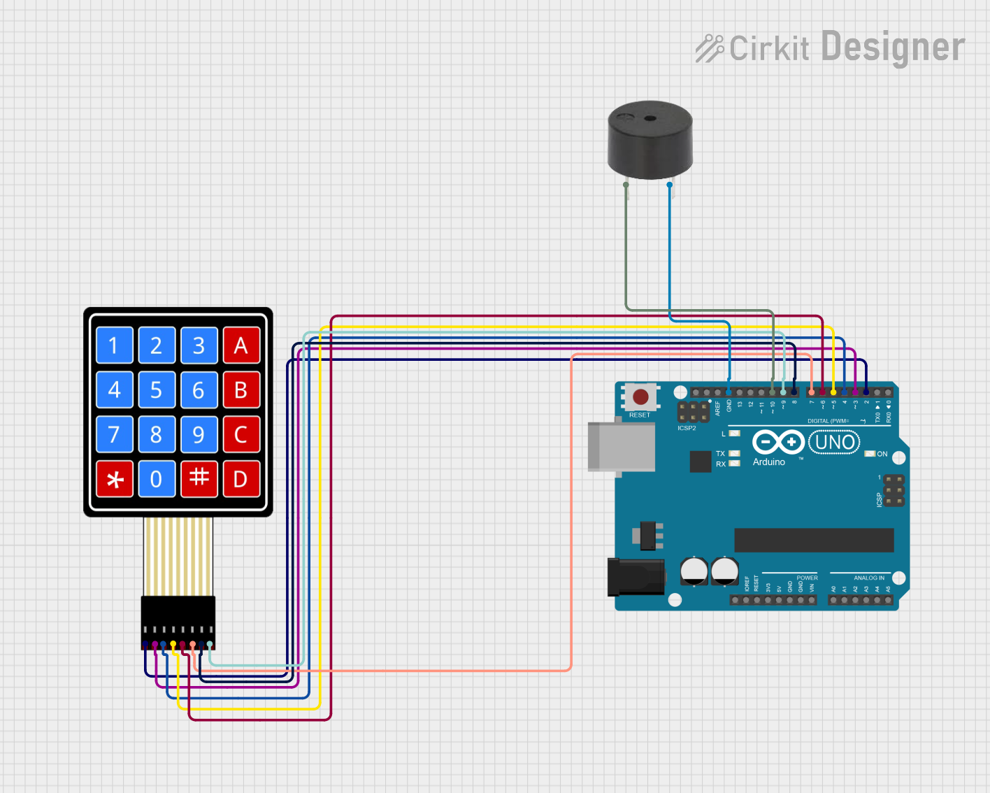
This circuit consists of an Arduino UNO microcontroller, a 4x4 membrane matrix keypad, and a buzzer. The Arduino UNO serves as the central processing unit, interfacing with the keypad for input and controlling the buzzer as an output device. The keypad allows for user interaction, and the buzzer provides audible feedback. The circuit is designed to capture inputs from the keypad and respond with appropriate actions, which could include generating sounds through the buzzer.
Component List
Arduino UNO
- Description: A microcontroller board based on the ATmega328P.
- Pins: UNUSED, IOREF, Reset, 3.3V, 5V, GND, Vin, A0-A5, SCL, SDA, AREF, D0-D13.
4X4 Membrane Matrix Keypad
- Description: An input device with 16 buttons arranged in a 4x4 grid.
- Pins: R1, R2, R3, R4, C1, C2, C3, C4.
Buzzer
- Description: An electromechanical component that produces sound.
- Pins: PIN, GND.
Wiring Details
Arduino UNO
- GND connected to Buzzer GND.
- D10 connected to Buzzer PIN.
- D9-D2 connected to Keypad C4-R1 respectively.
4X4 Membrane Matrix Keypad
- R1-R4 connected to Arduino UNO D2-D5 respectively.
- C1-C4 connected to Arduino UNO D6-D9 respectively.
Buzzer
- PIN connected to Arduino UNO D10.
- GND connected to Arduino UNO GND.
Documented Code
Arduino UNO Code (sketch.ino)
void setup() {
  // put your setup code here, to run once:

}

void loop() {
  // put your main code here, to run repeatedly:

}
Additional Notes (documentation.txt)
No additional code documentation provided.
This document provides an overview of the circuit components, their wiring, and the initial code structure for the Arduino UNO. Further development of the code is required to implement the desired functionality of the keypad and buzzer.