
Arduino UNO Multi-Sensor Monitoring System with RFID and Environmental Sensors
View and Edit Project In Cirkit Designer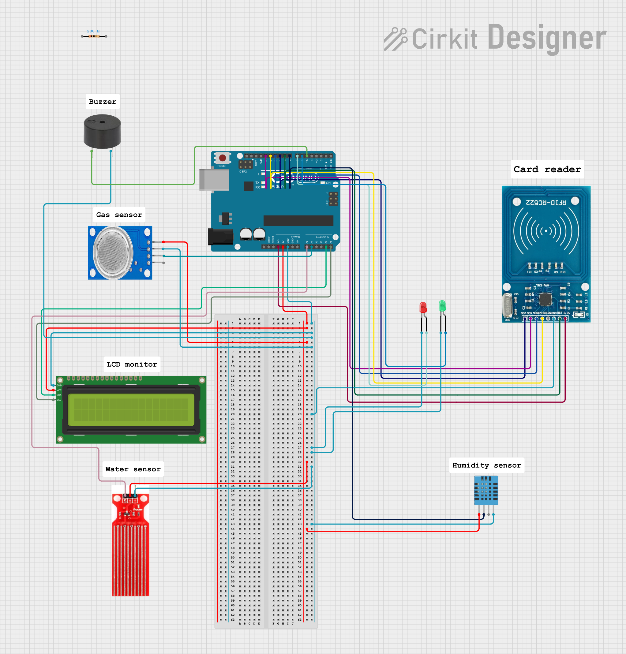
Circuit Documentation
Summary
This document provides a detailed overview of a circuit designed to interface various sensors and modules with an Arduino UNO microcontroller. The circuit includes an RFID-RC522 module for RFID communication, a DHT11 sensor for measuring humidity and temperature, a 16x2 I2C LCD for display, a water sensor for detecting the presence of water, an MQ135 sensor for air quality detection, a buzzer for audio signaling, and two LEDs (red and green) for visual indication. The circuit is powered by the Arduino UNO's onboard voltage regulators, and the components are interconnected through a series of electrical nets.
Component List
- Arduino UNO: A microcontroller board based on the ATmega328P, featuring digital and analog I/O pins.
- RFID-RC522: An RFID reader/writer module for contactless communication using radio frequency.
- DHT11 Humidity and Temperature Sensor: A sensor for measuring ambient humidity and temperature.
- 16x2 I2C LCD: A liquid crystal display with an I2C interface for showing text and numbers.
- Water Sensor: A sensor for detecting water presence and water level.
- MQ135: A sensor for detecting various gases such as CO2 and other harmful gases.
- Buzzer: An electronic component that produces sound.
- LED: Two Pin (red): A red light-emitting diode.
- LED: Two Pin (green): A green light-emitting diode.
- Resistor: A passive two-terminal electrical component that implements electrical resistance.
Wiring Details
Arduino UNO
- 5V Output: Powers the 16x2 I2C LCD, MQ135, Water sensor, and DHT11 sensor.
- 3.3V Output: Powers the RFID-RC522 module.
- GND: Common ground for the 16x2 I2C LCD, buzzer, MQ135, RFID-RC522, both LEDs, Water sensor, and DHT11 sensor.
- Analog Pins:
- A0: Connected to the Water sensor signal output.
- A1: Connected to the MQ135 analog output.
- I2C Pins:
- A4 (SDA): Connected to the 16x2 I2C LCD SDA pin.
- A5 (SCL): Connected to the 16x2 I2C LCD SCL pin.
- Digital Pins:
- D13: Connected to the RFID-RC522 SCK pin.
- D12: Connected to the RFID-RC522 MISO pin.
- D11: Connected to the RFID-RC522 MOSI pin.
- D10: Connected to the RFID-RC522 SDA pin.
- D9: Connected to the RFID-RC522 RST pin.
- D8: Connected to the DHT11 data pin.
- D7: Connected to the red LED anode through a resistor.
- D6: Connected to the green LED anode through a resistor.
- D5: Connected to the buzzer pin.
RFID-RC522
- VCC (3.3V): Powered by the Arduino UNO 3.3V output.
- RST: Connected to Arduino UNO D9.
- GND: Common ground with Arduino UNO.
- IRQ: Not connected.
- MISO: Connected to Arduino UNO D12.
- MOSI: Connected to Arduino UNO D11.
- SCK: Connected to Arduino UNO D13.
- SDA: Connected to Arduino UNO D10.
DHT11 Humidity and Temperature Sensor
- VDD: Powered by the Arduino UNO 5V output.
- DATA: Connected to Arduino UNO D8.
- NULL: Not connected.
- GND: Common ground with Arduino UNO.
16x2 I2C LCD
- GND: Common ground with Arduino UNO.
- VCC: Powered by the Arduino UNO 5V output.
- SDA: Connected to Arduino UNO A4.
- SCL: Connected to Arduino UNO A5.
Water Sensor
- Signal: Connected to Arduino UNO A0.
- VCC: Powered by the Arduino UNO 5V output.
- GND: Common ground with Arduino UNO.
MQ135
- VCC: Powered by the Arduino UNO 5V output.
- GND: Common ground with Arduino UNO.
- A0: Connected to Arduino UNO A1.
- D0: Not connected.
Buzzer
- PIN: Connected to Arduino UNO D5.
- GND: Common ground with Arduino UNO.
LED: Two Pin (red)
- Cathode: Common ground with Arduino UNO.
- Anode: Connected to Arduino UNO D7 through a resistor.
LED: Two Pin (green)
- Cathode: Common ground with Arduino UNO.
- Anode: Connected to Arduino UNO D6 through a resistor.
Resistor
- Pin1: Connected to the anode of the red LED.
- Pin2: Connected to Arduino UNO D7.
Documented Code
Arduino UNO Code (sketch.ino)
void setup() {
  // put your setup code here, to run once:

}

void loop() {
  // put your main code here, to run repeatedly:

}
The provided code is a template with empty setup() and loop() functions, which are the entry points for Arduino sketches. The setup() function is called once when the sketch starts and is used for initializing settings, while the loop() function runs repeatedly and contains the main logic of the sketch. Additional code is required to interact with the connected components.