Cirkit Designer
Your all-in-one circuit design IDE
Home /
Project Documentation
Arduino 101 Wi-Fi Enabled Temperature and Water Sensor System
Circuit Documentation
Summary
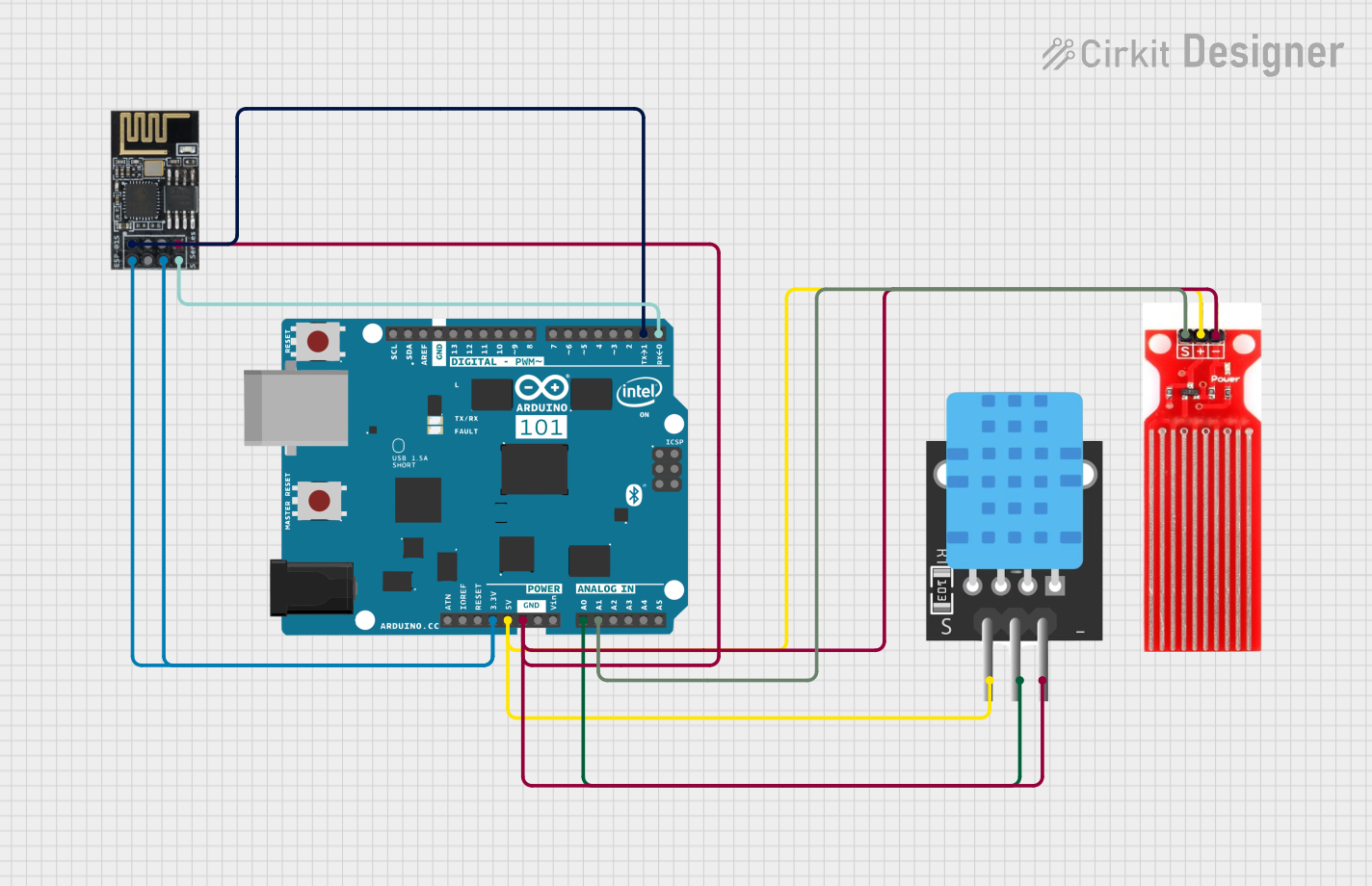
This circuit integrates an Arduino 101 microcontroller with a temperature sensor (TEMP), a WiFi module (ESP8266-01), and a water sensor. The Arduino 101 serves as the central controller, interfacing with the sensors and the WiFi module to collect data and potentially transmit it over a network.
Component List
Arduino 101
- Description: A microcontroller board based on the Intel Curie module.
- Pins: A5/SCL, A4/SDA, AREF, GND, D13/SCK, D12/MISO, D11 PWM/MOSI, D10 PWM/SS, D9 PWM, D8, D7, D6 PWM, D5 PWM, D4, D3 PWM, D2, D1/TX, D0/RX, AIN, ioref, RESET, 3V3, 5V, VIN, A0, A1, A2, A3, ICSP MISO, ICSP SCK, ICSP MOSI
TEMP (Temperature Sensor)
- Description: A sensor used to measure temperature.
- Pins: 5V, D3, GND
WiFi Module ESP8266-01
- Description: A WiFi module used for wireless communication.
- Pins: RX, GPIO0, GPIO2, GND, +3V3, Reset, CH-PD Chip power down, TX
Water Sensor
- Description: A sensor used to detect the presence of water.
- Pins: Signal, VCC, GND
Wiring Details
Arduino 101
- D1/TX is connected to RX of the WiFi module ESP8266-01.
- D0/RX is connected to TX of the WiFi module ESP8266-01.
- 3V3 is connected to +3V3 and CH-PD Chip power down of the WiFi module ESP8266-01.
- 5V is connected to 5V of the TEMP sensor and VCC of the Water sensor.
- GND is connected to GND of the TEMP sensor, WiFi module ESP8266-01, and Water sensor.
- A0 is connected to D3 of the TEMP sensor.
- A1 is connected to Signal of the Water sensor.
TEMP (Temperature Sensor)
- 5V is connected to 5V of the Arduino 101.
- D3 is connected to A0 of the Arduino 101.
- GND is connected to GND of the Arduino 101.
WiFi Module ESP8266-01
- RX is connected to D1/TX of the Arduino 101.
- TX is connected to D0/RX of the Arduino 101.
- +3V3 and CH-PD Chip power down are connected to 3V3 of the Arduino 101.
- GND is connected to GND of the Arduino 101.
Water Sensor
- Signal is connected to A1 of the Arduino 101.
- VCC is connected to 5V of the Arduino 101.
- GND is connected to GND of the Arduino 101.
Documented Code
Arduino 101 Code
void setup() {
  // put your setup code here, to run once:

}

void loop() {
  // put your main code here, to run repeatedly:

}
TEMP (Temperature Sensor) Code
void setup() {
  // put your setup code here, to run once:

}

void loop() {
  // put your main code here, to run repeatedly:

}
WiFi Module ESP8266-01 Code
void setup() {
  // put your setup code here, to run once:

}

void loop() {
  // put your main code here, to run repeatedly:

}
Water Sensor Code
void setup() {
  // put your setup code here, to run once:

}

void loop() {
  // put your main code here, to run repeatedly:

}
This documentation provides a comprehensive overview of the circuit, including a summary, detailed component descriptions, wiring details, and the code for each microcontroller.