
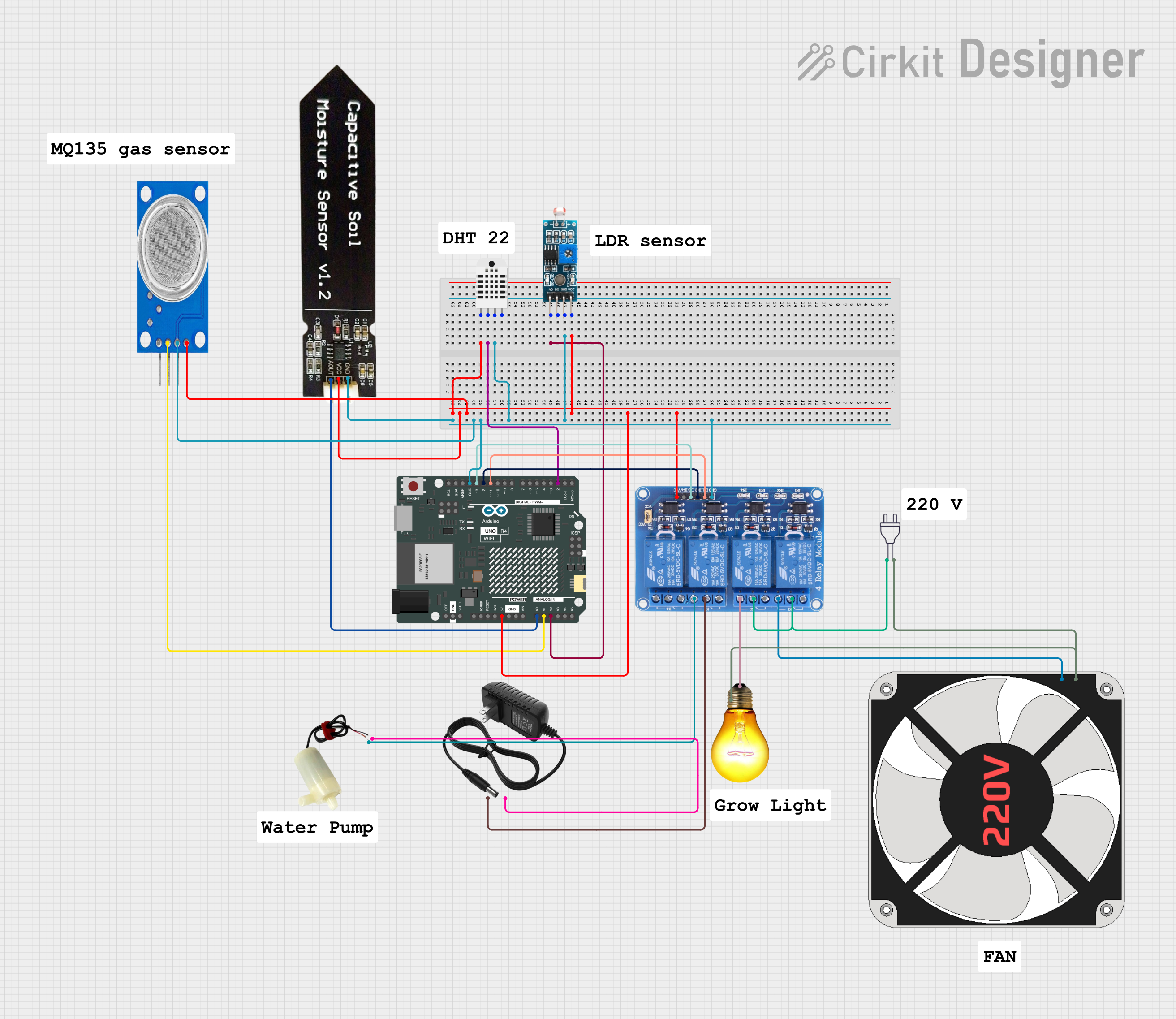
Circuit Documentation
Summary
This circuit is designed to automate a tomato plant in a greenhouse. It reads data from various sensors (humidity, temperature, soil moisture, air quality, and light intensity) and controls a relay module to manage a fan, an AC bulb, and a water pump. The system aims to maintain optimal conditions for the tomato plant.
Component List
Arduino UNO R4 WiFi
- Description: Microcontroller board used to read sensor data and control relays.
- Pins: OFF, GND, VRTC, IIC0_SCL, IIC0_SDA, 3V3, GPIO 41, GPIO 0, GPIO 42, GPIO 43, GPIO 44, BOOT, IOREF, RESET, 5V, VIN, A0, A1, A2, A3, A4, A5, RSPCKA, CIPO, COPI, D0/RX, D1/TX, D2, D3, D4, D5, D6, D7, D8, D9, D10, D11, D12, D13, AREF, SDA, SCL
Humidity and Temperature Sensor (RHT03)
- Description: Sensor to measure humidity and temperature.
- Pins: Vcc, Data-signal, GND 1, GND 2
Capacitive Soil Moisture Sensor V1.2
- Description: Sensor to measure soil moisture level.
- Pins: GND, VCC, AOUT
MQ135
- Description: Air quality sensor.
- Pins: VCC, GND, A0, D0
Module LDR
- Description: Light-dependent resistor module to measure light intensity.
- Pins: VCC, GND, DO, AO
Relay 4 Channel 5v
- Description: Relay module to control fan, AC bulb, and water pump.
- Pins: GND, IN1, IN2, IN3, IN4, VCC, COM1, COM2, COM3, COM4, NO1, NO2, NO3, NO4, NC1, NC2, NC3, NC4
220V Fan
- Description: Fan to control air circulation.
- Pins: N, L
Power 220V
- Description: Power supply for AC components.
- Pins: Hot wire, Neutral wire
AC Bulb
- Description: Bulb to provide light.
- Pins: P, N
5V Mini Water Pump
- Description: Water pump to irrigate the plant.
- Pins: Positive pin, Negative pin
12V Power Supply
- Description: Power supply for the water pump.
- Pins: +, -
Wiring Details
Arduino UNO R4 WiFi
5V connected to:
- VCC of Module LDR
- Vcc of Humidity and Temperature Sensor (RHT03)
- VCC of Relay 4 Channel 5v
- VCC of MQ135
- VCC of Capacitive Soil Moisture Sensor V1.2
GND connected to:
- GND of Module LDR
- GND 1 of Humidity and Temperature Sensor (RHT03)
- GND of Relay 4 Channel 5v
- GND of MQ135
- GND of Capacitive Soil Moisture Sensor V1.2
A0 connected to AOUT of Capacitive Soil Moisture Sensor V1.2
A1 connected to A0 of MQ135
A2 connected to AO of Module LDR
D2 connected to Data-signal of Humidity and Temperature Sensor (RHT03)
D11 connected to IN1 of Relay 4 Channel 5v
D12 connected to IN2 of Relay 4 Channel 5v
D13 connected to IN3 of Relay 4 Channel 5v
Humidity and Temperature Sensor (RHT03)
- Vcc connected to 5V of Arduino UNO R4 WiFi
- GND 1 connected to GND of Arduino UNO R4 WiFi
- Data-signal connected to D2 of Arduino UNO R4 WiFi
Capacitive Soil Moisture Sensor V1.2
- VCC connected to 5V of Arduino UNO R4 WiFi
- GND connected to GND of Arduino UNO R4 WiFi
- AOUT connected to A0 of Arduino UNO R4 WiFi
MQ135
- VCC connected to 5V of Arduino UNO R4 WiFi
- GND connected to GND of Arduino UNO R4 WiFi
- A0 connected to A1 of Arduino UNO R4 WiFi
Module LDR
- VCC connected to 5V of Arduino UNO R4 WiFi
- GND connected to GND of Arduino UNO R4 WiFi
- AO connected to A2 of Arduino UNO R4 WiFi
Relay 4 Channel 5v
- VCC connected to 5V of Arduino UNO R4 WiFi
- GND connected to GND of Arduino UNO R4 WiFi
- IN1 connected to D11 of Arduino UNO R4 WiFi
- IN2 connected to D12 of Arduino UNO R4 WiFi
- IN3 connected to D13 of Arduino UNO R4 WiFi
- COM1 connected to Hot wire of Power 220V
- COM2 connected to Hot wire of Power 220V
- COM3 connected to + of 12V Power Supply
- NO1 connected to L of 220V Fan
- NO2 connected to P of AC Bulb
- NO3 connected to Positive pin of 5V Mini Water Pump
220V Fan
- L connected to NO1 of Relay 4 Channel 5v
- N connected to Neutral wire of Power 220V
Power 220V
- Hot wire connected to COM1 and COM2 of Relay 4 Channel 5v
- Neutral wire connected to N of AC Bulb and N of 220V Fan
AC Bulb
- P connected to NO2 of Relay 4 Channel 5v
- N connected to Neutral wire of Power 220V
5V Mini Water Pump
- Positive pin connected to NO3 of Relay 4 Channel 5v
- Negative pin connected to - of 12V Power Supply
12V Power Supply
- + connected to COM3 of Relay 4 Channel 5v
- - connected to Negative pin of 5V Mini Water Pump
Code Documentation
/*
 * Arduino Sketch for Automating a Tomato Plant in a Greenhouse
 *
 * This sketch reads data from various sensors (humidity, temperature, soil moisture,
 * air quality, and light intensity) and controls a relay module to manage a fan,
 * an AC bulb, and a water pump. The system aims to maintain optimal conditions
 * for a tomato plant in a greenhouse.
 */

#include <DHT.h>

// Pin definitions
#define DHTPIN 2
#define DHTTYPE DHT22
#define SOIL_MOISTURE_PIN A0
#define AIR_QUALITY_PIN A1
#define LIGHT_SENSOR_PIN A2
#define RELAY_FAN_PIN 11
#define RELAY_BULB_PIN 12
#define RELAY_PUMP_PIN 13

// Initialize DHT sensor
DHT dht(DHTPIN, DHTTYPE);

// Timing variables
unsigned long previousMillis = 0;
const long interval = 2000;

void setup() {
  // Initialize serial communication
  Serial.begin(9600);

  // Initialize DHT sensor
  dht.begin();

  // Set relay pins as outputs
  pinMode(RELAY_FAN_PIN, OUTPUT);
  pinMode(RELAY_BULB_PIN, OUTPUT);
  pinMode(RELAY_PUMP_PIN, OUTPUT);

  // Initialize relays to off
  digitalWrite(RELAY_FAN_PIN, LOW);
  digitalWrite(RELAY_BULB_PIN, LOW);
  digitalWrite(RELAY_PUMP_PIN, LOW);
}

void loop() {
  unsigned long currentMillis = millis();

  if (currentMillis - previousMillis >= interval) {
    previousMillis = currentMillis;

    // Read humidity and temperature
    float humidity = dht.readHumidity();
    float temperature = dht.readTemperature();

    // Read soil moisture level
    int soilMoisture = analogRead(SOIL_MOISTURE_PIN);

    // Read air quality level
    int airQuality = analogRead(AIR_QUALITY_PIN);

    // Read light intensity level
    int lightIntensity = analogRead(LIGHT_SENSOR_PIN);

    // Print sensor values to serial monitor
    Serial.print("Humidity: ");
    Serial.print(humidity);
    Serial.print