Arduino-Controlled Robotic System with Servos, Ultrasonic Sensors, and Gear Motor
Circuit Documentation
Summary
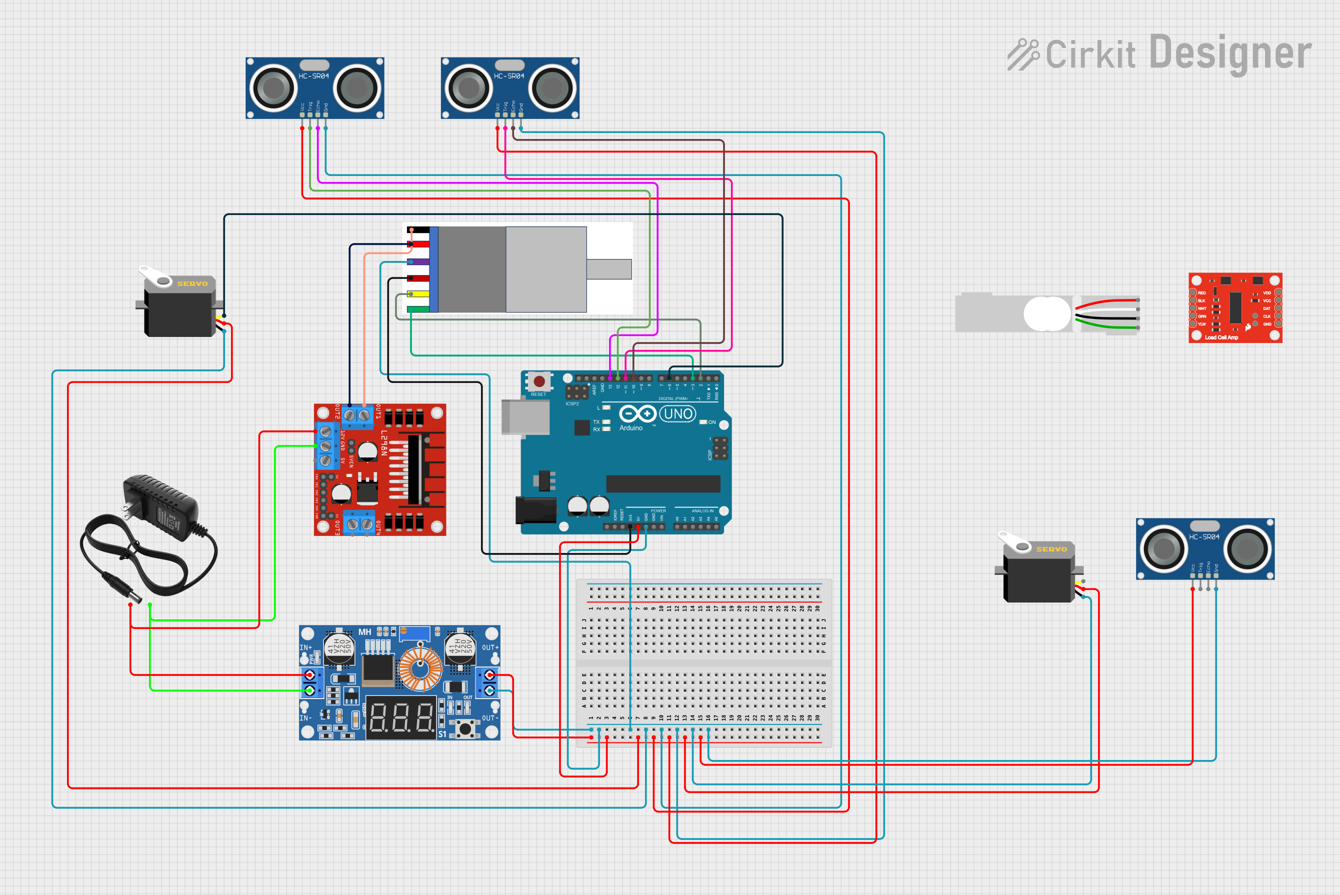
This circuit is designed to control a servo and a gear motor with an integrated encoder, read distance measurements from multiple HC-SR04 ultrasonic sensors, and manage power distribution using a step-down converter. The Arduino UNO serves as the central microcontroller unit to process inputs and outputs for controlling the servo and motor, as well as reading sensor data. The L298N DC motor driver interfaces with the gear motor to provide controlled power and direction. The XL4015 step-down module regulates the voltage for the circuit components. A load cell and its amplifier (HX711) are included in the parts list but are not connected in the provided net list.
Component List
- Servo: A motor with feedback control for precise angle positioning.
- L298N DC Motor Driver: A module for controlling the direction and speed of DC motors.
- Gear Motor with Integrated Encoder: A DC motor with a built-in encoder for position and speed feedback.
- SparkFun Load Cell Amplifier - HX711: An amplifier for reading measurements from a load cell.
- XL4015 5A DC Buck Step-down: A voltage regulator that steps down the input voltage to a lower output voltage.
- 12V Power Supply: Provides a 12V voltage source for the circuit.
- HC-SR04 Ultrasonic Sensor: A sensor for measuring distances using ultrasonic waves.
- Arduino UNO: A microcontroller board based on the ATmega328P, used for controlling the logic of the circuit.
- Load Cell - Red/white/black/green: A transducer that converts force into an electrical signal.
Wiring Details
Servo
- VCC: Connected to the 5V output from the step-down converter.
- GND: Connected to the ground net of the circuit.
- Pulse: Controlled by the Arduino UNO (D6).
L298N DC Motor Driver
- OUT1, OUT2: Connected to the Gear Motor.
- 12V: Powered by the 12V power supply.
- GND: Connected to the ground net of the circuit.
Gear Motor with Integrated Encoder
- MOTOR -/+: Connected to the L298N motor driver outputs.
- Encoder -: Connected to the ground net of the circuit.
- Encoder +: Connected to the 3.3V output from the Arduino UNO.
- Encoder A, Encoder B: Connected to the Arduino UNO (D2, D3).
XL4015 5A DC Buck Step-down
- Output +: Connected to the 5V net, powering the Arduino UNO and other 5V components.
- Output -: Connected to the ground net of the circuit.
- Input +: Connected to the +12V from the power supply.
- Input -: Connected to the ground net of the circuit.
12V Power Supply
- +: Provides power to the step-down converter and the motor driver.
- -: Connected to the ground net of the circuit.
HC-SR04 Ultrasonic Sensor
- VCC: Connected to the 5V net.
- GND: Connected to the ground net of the circuit.
- TRIG: Trigger pin controlled by the Arduino UNO (D11, D12).
- ECHO: Echo pin connected to the Arduino UNO (D10, D13).
Documented Code
Arduino UNO Code (sketch.ino)
void setup() {
  // put your setup code here, to run once:

}

void loop() {
  // put your main code here, to run repeatedly:

}
Note: The actual functionality of the code is not provided in the input. The user should implement the setup and loop functions to control the servo, read from the sensors, and manage the motor with the encoder.
Additional Documentation (documentation.txt)
No additional documentation code was provided.