
ESP32-Based Battery-Powered Hyperhidrosis Treatment Device with OLED Display and RTC
View and Edit Project In Cirkit Designer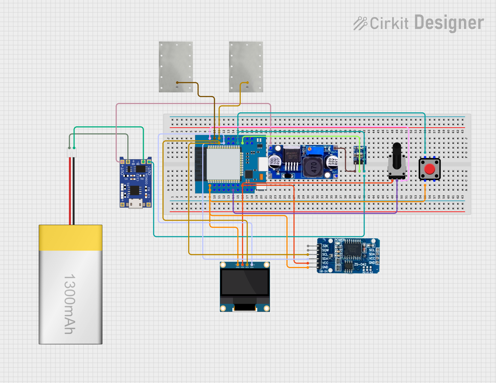
Circuit Documentation
Summary
This document provides a detailed overview of a circuit designed for a hyperhidrosis treatment device. The circuit includes an ESP32 microcontroller, an OLED display, a real-time clock (RTC), a rotary potentiometer, a pushbutton, a LiPoly battery, a TP4056 battery charger, an AMS1117 voltage regulator, and an LM2596 voltage regulator. The device is programmed to control current flow to electrodes based on user input and display relevant information on the OLED screen.
Component List
0.96" OLED
- Pins: GND, VDD, SCK, SDA
- Description: OLED display for visual output.
TP4056
- Pins: OUT-, B-, B+, OUT+, IN-, IN+
- Description: Lithium battery charger module.
LiPoly Battery (1300mAh)
- Pins: positive, negative
- Description: Power source for the circuit.
RTC DS3231
- Pins: 32K, SQW, SCL, SDA, VCC, GND
- Description: Real-time clock module.
LM2596
- Pins: IN, OUT
- Description: Buck converter for voltage regulation.
ams1117 3.3
- Pins: VIN, OUT, GND
- Description: 3.3V voltage regulator.
Rotary Potentiometer
- Pins: leg1, wiper, leg2
- Description: Adjustable resistor for user input.
- Properties: Resistance: 10000 Ohms
Red Pushbutton
- Pins: Pin 2, Pin 1, Pin 3, Pin 4
- Description: User input button.
Aluminum Sheet
- Pins: -, +
- Description: Electrode for current flow.
ESP32 Mini
- Pins: GND, GPIO27, GPIO25, GPIO32, TDI, GPIO4, GPIO0, GPIO2, SD1, CLK, RXD, TXD, GPIO22, GPIO21, GPIO17, GPIO16, VCC, TD0, SD0, RST, SVP, GPIO26, GPIO18, GPIO19, GPIO23, GPIO5, 3.3V, TCK, SD3, NC, SVN, GPIO35, GPIO33, GPIO34, TMS, SD2
- Description: Microcontroller for processing and control.
Wiring Details
0.96" OLED
- GND: Connected to GND of ESP32 Mini, RTC DS3231, and Red Pushbutton.
- VDD: Connected to 3.3V of ESP32 Mini, VCC of RTC DS3231.
- SCK: Connected to GPIO22 of ESP32 Mini, SCL of RTC DS3231.
- SDA: Connected to GPIO21 of ESP32 Mini, SDA of RTC DS3231.
TP4056
- OUT-: Connected to GND of ESP32 Mini, ams1117 3.3, and Red Pushbutton.
- B-: Connected to negative of LiPoly Battery.
- B+: Connected to positive of LiPoly Battery.
- OUT+: Connected to IN of LM2596.
LiPoly Battery (1300mAh)
- positive: Connected to B+ of TP4056.
- negative: Connected to B- of TP4056.
RTC DS3231
- GND: Connected to GND of ESP32 Mini, 0.96" OLED, and Red Pushbutton.
- VCC: Connected to 3.3V of ESP32 Mini, VDD of 0.96" OLED.
- SCL: Connected to GPIO22 of ESP32 Mini, SCK of 0.96" OLED.
- SDA: Connected to GPIO21 of ESP32 Mini, SDA of 0.96" OLED.
LM2596
- IN: Connected to OUT+ of TP4056.
- OUT: Connected to VIN of ams1117 3.3.
ams1117 3.3
- VIN: Connected to OUT of LM2596.
- OUT: Connected to GPIO2 and VCC of ESP32 Mini.
- GND: Connected to GND of ESP32 Mini, TP4056, and Red Pushbutton.
Rotary Potentiometer
- leg1: Connected to 3.3V of ESP32 Mini.
- wiper: Connected to GPIO34 of ESP32 Mini.
- leg2: Connected to GND of ESP32 Mini, TXD of ESP32 Mini.
Red Pushbutton
- Pin 1: Connected to GND of ESP32 Mini, TP4056, and ams1117 3.3.
- Pin 2: Connected to RST of ESP32 Mini, GND of ESP32 Mini, RTC DS3231, and 0.96" OLED.
Aluminum Sheet
- +: Connected to GPIO27 and RXD of ESP32 Mini.
- -: Not connected.
ESP32 Mini
- GND: Connected to GND of RTC DS3231, 0.96" OLED, Red Pushbutton, Rotary Potentiometer, TP4056, and ams1117 3.3.
- 3.3V: Connected to VCC of RTC DS3231, VDD of 0.96" OLED, and leg1 of Rotary Potentiometer.
- GPIO27: Connected to + of Aluminum Sheet.
- GPIO25: Connected to GPIO22 of ESP32 Mini.
- GPIO32: Connected to GPIO21 of ESP32 Mini.
- GPIO21: Connected to SDA of RTC DS3231, SDA of 0.96" OLED.
- GPIO22: Connected to SCL of RTC DS3231, SCK of 0.96" OLED.
- GPIO34: Connected to wiper of Rotary Potentiometer.
- GPIO0: Connected to GND of ESP32 Mini, TP4056, and ams1117 3.3.
- GPIO2: Connected to OUT of ams1117 3.3.
- GPIO23: Connected to GPIO34 of ESP32 Mini.
- GPIO4: Connected to GPIO16 of ESP32 Mini.
- GPIO16: Connected to GPIO4 of ESP32 Mini.
- GPIO17: Connected to TDI of ESP32 Mini.
- TDI: Connected to GPIO17 of ESP32 Mini.
- SD1: Connected to TD0 of ESP32 Mini.
- TD0: Connected to SD1 of ESP32 Mini.
- CLK: Connected to SD0 of ESP32 Mini.
- SD0: Connected to CLK of ESP32 Mini.
- SVP: Connected to NC of ESP32 Mini.
- NC: Connected to SVP of ESP32 Mini.
- GPIO26: Connected to SVN of ESP32 Mini.
- SVN: Connected to GPIO26 of ESP32 Mini.
- GPIO18: Connected to GPIO35 of ESP32 Mini.
- GPIO35: Connected to GPIO18 of ESP32 Mini.
- GPIO19: Connected to GPIO33 of ESP32 Mini.
- GPIO33: Connected to GPIO19 of ESP32 Mini.
- GPIO5: Connected to TMS of ESP32 Mini.
- TMS: Connected to GPIO5 of ESP32 Mini.
- TCK: Connected to SD2 of ESP32 Mini.
- SD2: Connected to TCK of ESP32 Mini.
- SD3: Not connected.
Code Documentation
#include <Wire.h>
#include <Adafruit_GFX.h>
#include <Adafruit_SSD1306.h>
#include <RTClib.h>

// Pin Definitions
#define POT_PIN 34
#define BUTTON_PIN 0
#define ELECTRODE_PIN_POS 25 // Positive electrode
#define ELECTRODE_PIN_NEG 26 // Negative electrode
#define BATTERY_PIN 35

// OLED Display
#define SCREEN_WIDTH 128
#define SCREEN_HEIGHT 64
Adafruit_SSD1306 display(SCREEN_WIDTH, SCREEN_HEIGHT, &Wire, -1);

// RTC
RTC_DS3231 rtc;

// Variables
int sessionTime = 600; // 10 minutes session
int currentFlow = 0;
bool sessionActive = false;
unsigned long startTime;
unsigned long currentTime;

void setup() {
  // Initialize Serial
  Serial.begin(115200);

  // Initialize OLED
  if (!display.begin(SSD1306_I2C_ADDRESS, OLED_RESET)) {
    Serial.println(F("SSD1306 allocation failed"));
    for (;;);
  }
  display.display();
  delay(2000);
  display.clearDisplay();

  // Initialize RTC
  if (!rtc.begin()) {
    Serial.println("Couldn't find RTC");
    while (1);
  }

  // Initialize Pins
  pinMode(POT_PIN, INPUT);
  pinMode(BUTTON_PIN, INPUT_PULLUP);
  pinMode(ELECTRODE_PIN_POS, OUTPUT);
  pinMode(ELECTRODE_PIN_NEG, OUTPUT);
  pinMode(BATTERY_PIN, INPUT);

  // Setup PWM channels
  const int freq = 5000;
  const int ledChannel =