
ESP32 CAM-Based Wi-Fi Controlled Smart Door Lock with OLED Display
View and Edit Project In Cirkit Designer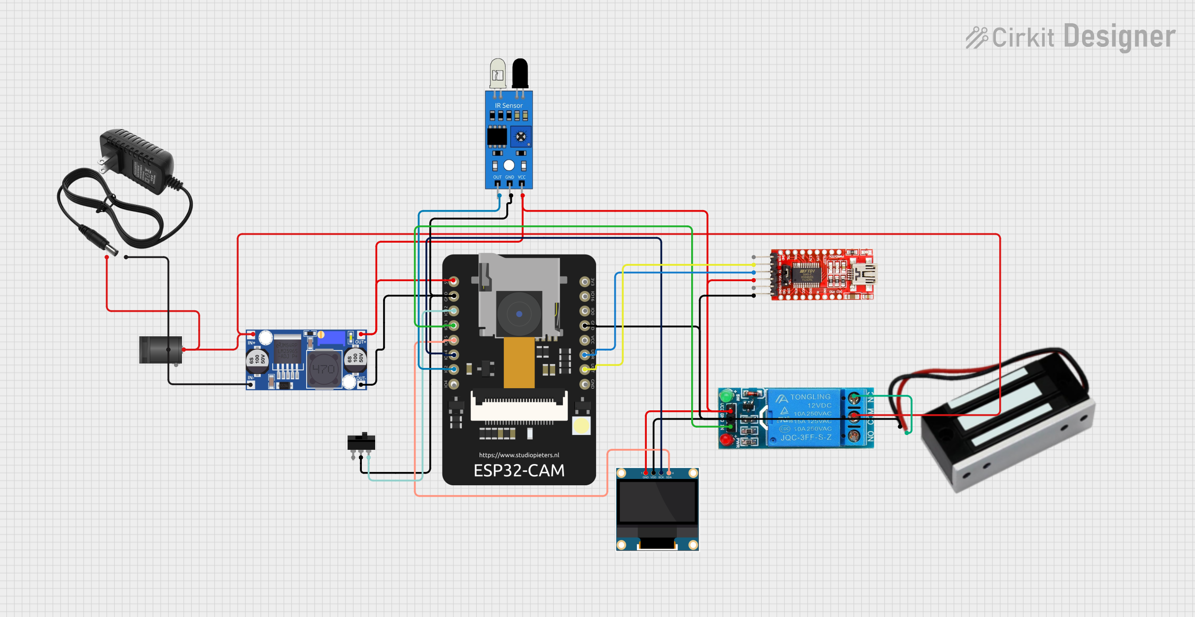
Circuit Documentation
Summary
This circuit is designed to control an electronic door lock using an ESP32 CAM module. The system includes an OLED display for status updates, an IR sensor for motion detection, a relay to control the door lock, and a toggle switch to switch between access and registration modes. The ESP32 CAM connects to a Wi-Fi network to communicate with a server for face recognition and registration.
Component List
ESP32 CAM
- Description: A microcontroller with a built-in camera module.
- Pins: 5V, GND, GPIO12, GPIO13, GPIO15, GPIO14, GPIO2, GPIO4, 3.3V, GPIO16, GPIO0, 3.3V / 5V / P_OUT, GPIO3 / RX, GPIO1 / TX
0.96" OLED
- Description: A small OLED display for showing status messages.
- Pins: GND, VDD, SCK, SDA
12V SINGLE CHANNEL RELAY
- Description: A relay module to control the electronic door lock.
- Pins: NC, COM, NO, IN, GND, VCC
12V Power Supply
- Description: A power supply to provide 12V DC.
- Pins: +, -
Buck Converter
- Description: A DC-DC converter to step down voltage.
- Pins: IN+, IN-, OUT+, OUT-
IR Sensor
- Description: An infrared sensor for motion detection.
- Pins: out, gnd, vcc
FTDI Programmer
- Description: A USB-to-serial converter for programming the ESP32 CAM.
- Pins: DTR, RX, TX, VCC, CTS, GND
Toggle Switch
- Description: A switch to toggle between access and registration modes.
- Pins: L1, COM, L2
2.1mm DC Barrel Jack
- Description: A connector for the 12V power supply.
- Pins: switch, sleeve, center
EML
- Description: An electronic door lock.
- Pins: -, +
Wiring Details
ESP32 CAM
- 5V: Connected to VCC of the 12V SINGLE CHANNEL RELAY, vcc of the IR sensor, GND of the 0.96" OLED, OUT+ of the Buck converter, and VCC of the FTDI Programmer.
- GND: Connected to gnd of the IR sensor, COM of the Toggle Switch, OUT- of the Buck converter, GND of the 12V SINGLE CHANNEL RELAY, VDD of the 0.96" OLED, GND of the FTDI Programmer, and - of the EML.
- GPIO12: Connected to L2 of the Toggle Switch.
- GPIO13: Connected to IN of the 12V SINGLE CHANNEL RELAY.
- GPIO15: Connected to SDA of the 0.96" OLED.
- GPIO14: Connected to SCK of the 0.96" OLED.
- GPIO2: Connected to out of the IR sensor.
- GPIO3 / RX: Connected to TX of the FTDI Programmer.
- GPIO1 / TX: Connected to RX of the FTDI Programmer.
0.96" OLED
- GND: Connected to 5V of the ESP32 CAM.
- VDD: Connected to GND of the ESP32 CAM.
- SCK: Connected to GPIO14 of the ESP32 CAM.
- SDA: Connected to GPIO15 of the ESP32 CAM.
12V SINGLE CHANNEL RELAY
- VCC: Connected to 5V of the ESP32 CAM.
- GND: Connected to GND of the ESP32 CAM.
- IN: Connected to GPIO13 of the ESP32 CAM.
- NC: Connected to + of the EML.
- COM: Connected to + of the 12V Power Supply, IN+ of the Buck converter, and center of the 2.1mm DC Barrel Jack.
12V Power Supply
- +: Connected to COM of the 12V SINGLE CHANNEL RELAY.
- -: Connected to IN- of the Buck converter and switch of the 2.1mm DC Barrel Jack.
Buck Converter
- IN+: Connected to COM of the 12V SINGLE CHANNEL RELAY.
- IN-: Connected to - of the 12V Power Supply.
- OUT+: Connected to 5V of the ESP32 CAM.
- OUT-: Connected to GND of the ESP32 CAM.
IR Sensor
- out: Connected to GPIO2 of the ESP32 CAM.
- gnd: Connected to GND of the ESP32 CAM.
- vcc: Connected to 5V of the ESP32 CAM.
FTDI Programmer
- VCC: Connected to 5V of the ESP32 CAM.
- GND: Connected to GND of the ESP32 CAM.
- TX: Connected to GPIO3 / RX of the ESP32 CAM.
- RX: Connected to GPIO1 / TX of the ESP32 CAM.
Toggle Switch
- COM: Connected to GND of the ESP32 CAM.
- L2: Connected to GPIO12 of the ESP32 CAM.
2.1mm DC Barrel Jack
- center: Connected to COM of the 12V SINGLE CHANNEL RELAY.
- switch: Connected to - of the 12V Power Supply.
EML
- +: Connected to NC of the 12V SINGLE CHANNEL RELAY.
- -: Connected to GND of the ESP32 CAM.
Documented Code
// AUTHOR : HARIHARAN P
// COMPANY : AQUAGROUP
// DATE :13.12.2024
//FINAL VC DEVICE SOURCE FILE

#include "esp_camera.h"
#include <WiFi.h>
#include <HTTPClient.h>
#include <Wire.h>
#include <Adafruit_GFX.h>
#include <Adafruit_SSD1306.h>

// WiFi credentials
const char *ssid = "PLC&IOT";
const char *password = "Aqua@12345";
const char *serverURL = "http://192.168.0.58:5000/api/verify";  // Python server API for face recognition
const char *registerURL = "http://192.168.0.58:5000/api/register"; // API for registration

#define DOOR_PIN 13  // Pin to control the door lock (EM lock)
#define SLIDE_SWITCH_PIN 12  // Slide switch to toggle between modes
#define DEVICE_ID "6477744974"
#define SCREEN_WIDTH 128
#define SCREEN_HEIGHT 64
#define OLED_RESET    -1  // OLED reset pin, not used
#define SCREEN_ADDRESS 0x3C  // I2C address for the OLED display

// Static IP configuration
IPAddress local_IP(192, 168, 0, 5);     // Desired static IP address
IPAddress gateway(192, 168, 0, 1);       // Gateway address
IPAddress subnet(255, 255, 255, 0);      // Subnet mask
IPAddress primaryDNS(8, 8, 8, 8);        // Primary DNS (optional)
IPAddress secondaryDNS(8, 8, 4, 4);      // Secondary DNS (optional)

// Initialize I2C bus
TwoWire I2Cbus = TwoWire(0);

// Create an OLED display object
Adafruit_SSD1306 display(SCREEN_WIDTH, SCREEN_HEIGHT, &I2Cbus, OLED_RESET);

// Initialize camera settings
camera_fb_t* fb = NULL;

void setup() {
  Serial.begin(115200);

  // Setup Door Control Pin
  pinMode(DOOR_PIN, OUTPUT);
  digitalWrite(DOOR_PIN, LOW);  // Keep the door locked initially

  pinMode(SLIDE_SWITCH_PIN, INPUT_PULLUP); // Setup Slide Switch

  // Setup I2C for OLED
  I2Cbus.begin(15, 14);  // SDA, SCL pins for the OLED

  // Initialize OLED display
  if (!display.begin(SSD1306_SWITCHCAPVCC, SCREEN_ADDRESS)) {
    Serial.println("SSD1306 allocation failed");
    for (;;); // Don't proceed, loop forever
  }
  display.clearDisplay();
  display.setTextSize(1);
  display.setTextColor(SSD1306_WHITE);
  display.setCursor(0, 10);
  display.println("Initializing...");
  display.display();

  // Configure Wi-Fi with static IP
  if (!WiFi.config(local_IP, gateway, subnet, primaryDNS, secondaryDNS)) {
    Serial.println("STA Failed to configure");
    display.clearDisplay();
    display.setCursor(0, 10);
    display.println("IP Config Fail");
    display.display();
    for (;;);  // Halt if static IP setup fails
  }

  // Initialize Wi-Fi
  WiFi.begin(ssid, password);
  while (WiFi.status() != WL_CONNECTED) {
    delay(500);
    Serial.print(".");
    display.setCursor(0, 20);