
ESP32-Based Flame Detection and Water Pump Control System with Servo Mechanism
View and Edit Project In Cirkit Designer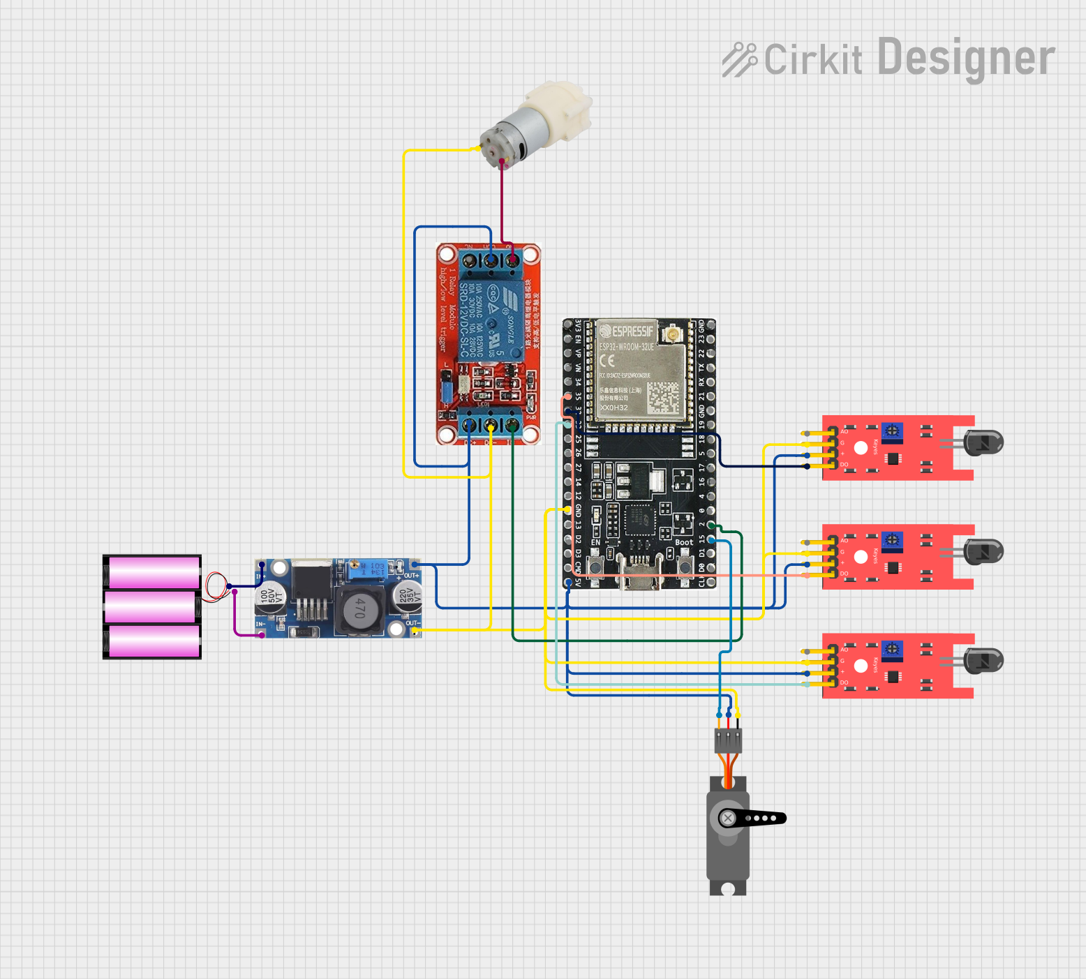
Circuit Documentation
Summary
This circuit is designed to control a water pump and a servo motor based on inputs from multiple KY-026 Flame Sensors. The circuit uses an ESP32 microcontroller to process sensor data and control the relay and servo motor. The system is powered by a 12V battery, with a 48V to 5V converter providing the necessary voltage levels for the components.
Component List
Water Pump 12V
- Description: A 12V water pump used for fluid movement.
- Pins: +, -
Servo
- Description: A servo motor used for precise control of angular position.
- Pins: GND, VCC, PWM
12V Relay
- Description: A relay module used to control high-power devices.
- Pins: NO, COM, NC, IN, DC-, DC+
KY-026 Flame Sensor
- Description: A flame sensor used to detect the presence of fire.
- Pins: A0, GND, VCC, D0
48V to 5V Converter
- Description: A voltage converter to step down from 48V to 5V.
- Pins: out+, out--, in+, in--
ESP32-WROOM-32UE
- Description: A microcontroller with Wi-Fi and Bluetooth capabilities.
- Pins: 3v3, EN, VP, VN, 34, 35, 32, 33, 25, 26, 27, 14, 12, GND, 13, D2, D3, 5V, 23, 22, TX, RX, 21, 19, 18, 5, 17, 16, 4, 0, 2, 15, D1, D0, CKL
Battery 12V
- Description: A 12V battery used to power the circuit.
- Pins: +, -
Wiring Details
Water Pump 12V
- Pin +: Connected to NO pin of the 12V Relay.
- Pin -: Connected to GND net.
Servo
- Pin GND: Connected to GND net.
- Pin VCC: Connected to VCC net.
- Pin PWM: Connected to pin 15 of the ESP32.
12V Relay
- Pin NO: Connected to + pin of the Water Pump.
- Pin COM: Connected to VCC net.
- Pin NC: Not connected.
- Pin IN: Connected to pin 2 of the ESP32.
- Pin DC-: Connected to GND net.
- Pin DC+: Connected to VCC net.
KY-026 Flame Sensor (Instance 1)
- Pin A0: Not connected.
- Pin GND: Connected to GND net.
- Pin VCC: Connected to VCC net.
- Pin D0: Connected to pin 35 of the ESP32.
KY-026 Flame Sensor (Instance 2)
- Pin A0: Not connected.
- Pin GND: Connected to GND net.
- Pin VCC: Connected to VCC net.
- Pin D0: Connected to pin 32 of the ESP32.
KY-026 Flame Sensor (Instance 3)
- Pin A0: Not connected.
- Pin GND: Connected to GND net.
- Pin VCC: Connected to VCC net.
- Pin D0: Connected to pin 33 of the ESP32.
48V to 5V Converter
- Pin out+: Connected to VCC net.
- Pin out--: Connected to GND net.
- Pin in+: Connected to + pin of the 12V Battery.
- Pin in--: Connected to - pin of the 12V Battery.
ESP32-WROOM-32UE
- Pin GND: Connected to GND net.
- Pin 5V: Connected to VCC net.
- Pin 32: Connected to D0 pin of KY-026 Flame Sensor (Instance 2).
- Pin 33: Connected to D0 pin of KY-026 Flame Sensor (Instance 3).
- Pin 35: Connected to D0 pin of KY-026 Flame Sensor (Instance 1).
- Pin 2: Connected to IN pin of the 12V Relay.
- Pin 15: Connected to PWM pin of the Servo.
Battery 12V
- Pin +: Connected to in+ pin of the 48V to 5V Converter.
- Pin -: Connected to in-- pin of the 48V to 5V Converter.
Documented Code
#include <Servo.h>

const int leftSensorPin = 35;
const int middleSensorPin = 32;
const int rightSensorPin = 33;
const int relayPin = 2;
const int servoPin = 15;

Servo myServo;

void setup() {
  pinMode(leftSensorPin, INPUT);
  pinMode(middleSensorPin, INPUT);
  pinMode(rightSensorPin, INPUT);
  pinMode(relayPin, OUTPUT);
  myServo.attach(servoPin);
  myServo.write(90); // Initial position
  digitalWrite(relayPin, LOW); // Relay off initially
}

void loop() {
  int leftSensorValue = digitalRead(leftSensorPin);
  int middleSensorValue = digitalRead(middleSensorPin);
  int rightSensorValue = digitalRead(rightSensorPin);

  if (leftSensorValue == HIGH && middleSensorValue == LOW && rightSensorValue == LOW) {
    myServo.write(0); // Turn servo to the left
    digitalWrite(relayPin, HIGH); // Activate relay
  } else if (rightSensorValue == HIGH && middleSensorValue == LOW && leftSensorValue == LOW) {
    myServo.write(180); // Turn servo to the right
    digitalWrite(relayPin, HIGH); // Activate relay
  } else if (middleSensorValue == HIGH) {
    myServo.write(90); // Keep servo in the middle
    digitalWrite(relayPin, HIGH); // Activate relay
  } else {
    digitalWrite(relayPin, LOW); // Deactivate relay
  }

  delay(100); // Small delay to debounce sensor readings
}
This code initializes the ESP32 microcontroller to read inputs from the flame sensors and control the servo motor and relay based on the sensor readings. The servo motor is set to different positions based on which sensor detects a flame, and the relay is activated accordingly.