
Circuit Documentation
Summary
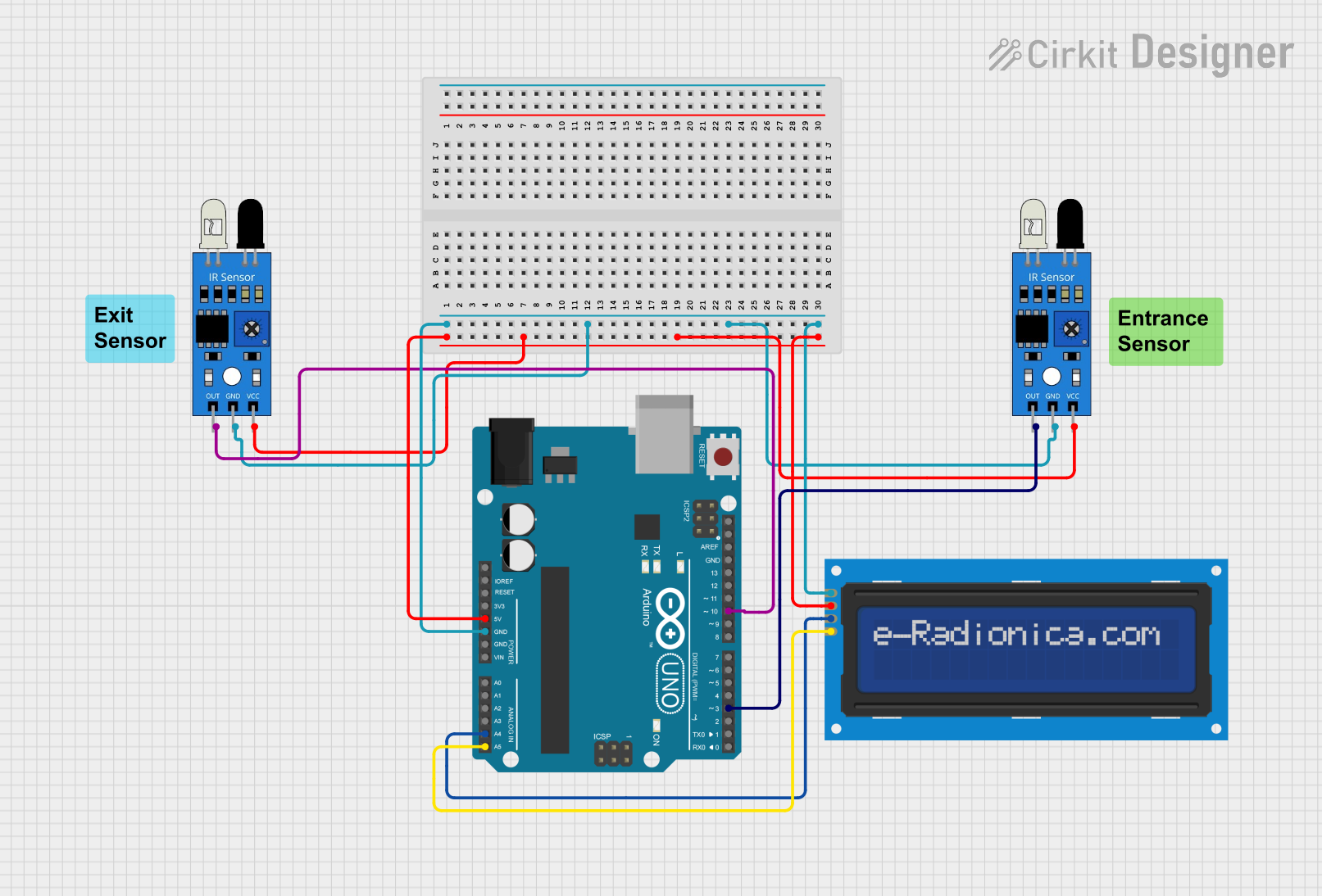
This circuit integrates an Arduino UNO microcontroller with two IR sensors and an LCD screen that communicates via the I2C protocol. The Arduino UNO is responsible for controlling the sensors and displaying information on the LCD screen. The IR sensors are powered by the Arduino and send their output signals back to it for processing. The LCD screen is used to display data or status information as programmed.
Component List
Arduino UNO
- Description: A microcontroller board based on the ATmega328P.
- Pins: UNUSED, IOREF, Reset, 3.3V, 5V, GND, Vin, A0-A5, SCL, SDA, AREF, D0-D13.
IR Sensor
- Description: An infrared sensor capable of detecting infrared light.
- Pins: out, gnd, vcc.
LCD Screen 16x2 I2C
- Description: A 16x2 character LCD display with an I2C interface.
- Pins: SCL, SDA, VCC, GND.
Wiring Details
Arduino UNO
- 5V connected to:
- VCC of both IR sensors
- VCC of the LCD screen
- GND connected to:
- GND of both IR sensors
- GND of the LCD screen
- A4 (SDA) connected to SDA of the LCD screen
- A5 (SCL) connected to SCL of the LCD screen
- D10 connected to the 'out' pin of one IR sensor
- D3 connected to the 'out' pin of the other IR sensor
IR Sensor 1
- out connected to D10 on the Arduino UNO
- gnd connected to GND on the Arduino UNO
- vcc connected to 5V on the Arduino UNO
IR Sensor 2
- out connected to D3 on the Arduino UNO
- gnd connected to GND on the Arduino UNO
- vcc connected to 5V on the Arduino UNO
LCD Screen 16x2 I2C
- SCL connected to A5 on the Arduino UNO
- SDA connected to A4 on the Arduino UNO
- VCC connected to 5V on the Arduino UNO
- GND connected to GND on the Arduino UNO
Documented Code
Arduino UNO Code (sketch.ino)
void setup() {
  // put your setup code here, to run once:

}

void loop() {
  // put your main code here, to run repeatedly:

}
Additional Notes (documentation.txt)
No additional code documentation was provided.