Arduino-Based Smart Sensor System with GSM Alerts
Circuit Documentation
Summary
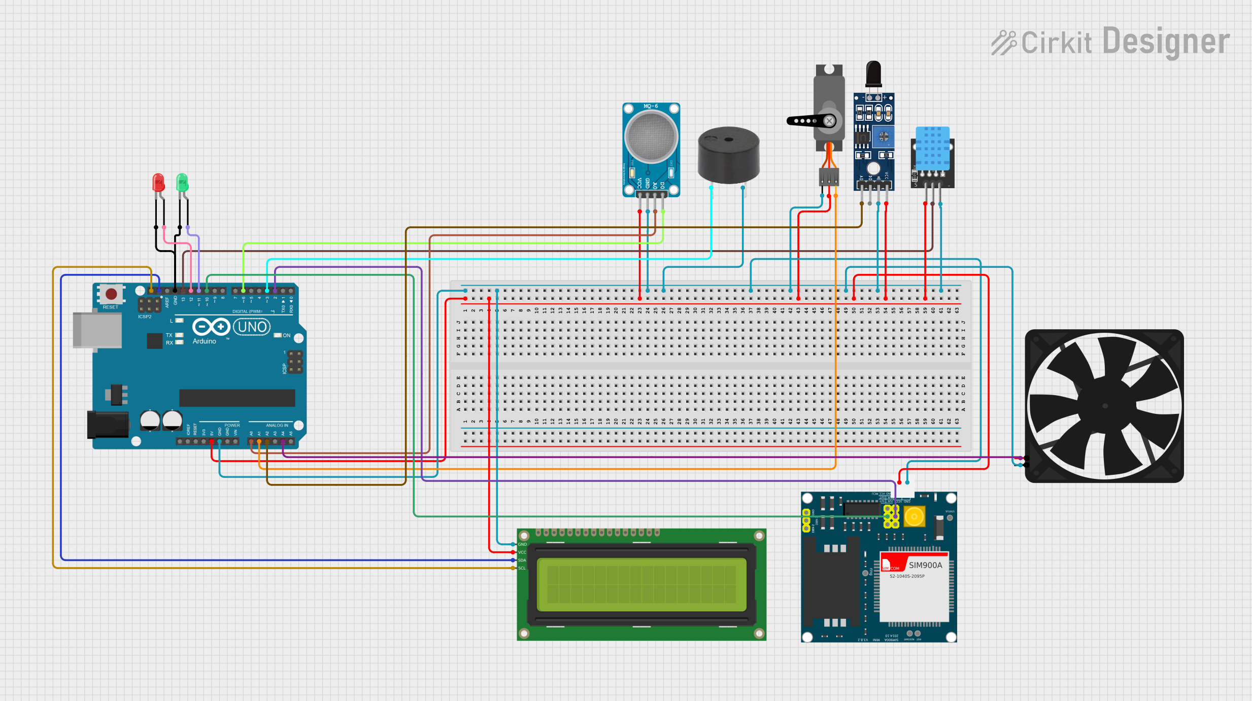
This circuit is designed to read values from a DHT11 sensor, Flame sensor, and MQ-6 gas sensor. It displays temperature and humidity on an LCD screen, detects fire and gas presence, and takes appropriate actions such as turning on LEDs, activating a buzzer, rotating a servo motor, turning on a fan, and sending messages via a GSM module.
Component List
LED: Two Pin (red)
- Pins: cathode, anode
- Description: Red LED used for indicating alerts.
LED: Two Pin (green)
- Pins: cathode, anode
- Description: Green LED used for indicating normal operation.
Buzzer
- Pins: PIN, GND
- Description: Buzzer used for audible alerts.
Servo
- Pins: GND, VCC, PWM
- Description: Servo motor used for mechanical actions.
MQ-6 SENSOR LPG GAS
- Pins: VCC, GND, A0, D0
- Description: Gas sensor used for detecting LPG gas.
Fan
- Pins: GND, 5V
- Description: Fan used for ventilation.
SIM900A
- Pins: GND, DB9-3 (RXD), DB9-2 (TXD), 5V, 3VR, 5VR, 3VT, 5VT, VCC, Ring, RESTART, RESET, STATUS
- Description: GSM module used for sending SMS alerts.
16x2 I2C LCD
- Pins: GND, VCC, SDA, SCL
- Description: LCD screen used for displaying sensor readings.
Sensor SHT113 Flame
- Pins: A0, D0, GND, VCC
- Description: Flame sensor used for detecting fire.
KY-015 DHT11
- Pins: 5V, S, GND
- Description: Temperature and humidity sensor.
Arduino UNO
- Pins: UNUSED, IOREF, Reset, 3.3V, 5V, GND, Vin, A0, A1, A2, A3, A4, A5, SCL, SDA, AREF, D13, D12, D11, D10, D9, D8, D7, D6, D5, D4, D3, D2, D1, D0
- Description: Microcontroller used for controlling the circuit.
Wiring Details
LED: Two Pin (red)
- cathode: Connected to GND of Arduino UNO
- anode: Connected to D12 of Arduino UNO
LED: Two Pin (green)
- cathode: Connected to GND of Arduino UNO
- anode: Connected to D11 of Arduino UNO
Buzzer
- PIN: Connected to D3 of Arduino UNO
- GND: Connected to GND of Arduino UNO
Servo
- GND: Connected to GND of Arduino UNO
- VCC: Connected to 5V of Arduino UNO
- PWM: Connected to A1 of Arduino UNO
MQ-6 SENSOR LPG GAS
- VCC: Connected to 5V of Arduino UNO
- GND: Connected to GND of Arduino UNO
- A0: Connected to A0 of Arduino UNO
- D0: Connected to D6 of Arduino UNO
Fan
- GND: Connected to GND of Arduino UNO
- 5V: Connected to A4 of Arduino UNO
SIM900A
- GND: Connected to GND of Arduino UNO
- 5V: Connected to 5V of Arduino UNO
- 5VT: Connected to D10 of Arduino UNO
- 5VR: Connected to D2 of Arduino UNO
16x2 I2C LCD
- GND: Connected to GND of Arduino UNO
- VCC: Connected to 5V of Arduino UNO
- SDA: Connected to SDA of Arduino UNO
- SCL: Connected to SCL of Arduino UNO
Sensor SHT113 Flame
- A0: Connected to A2 of Arduino UNO
- GND: Connected to GND of Arduino UNO
- VCC: Connected to 5V of Arduino UNO
KY-015 DHT11
- 5V: Connected to 5V of Arduino UNO
- S: Connected to D13 of Arduino UNO
- GND: Connected to GND of Arduino UNO
Arduino UNO
- 5V: Connected to VCC of 16x2 I2C LCD, MQ-6 SENSOR LPG GAS, Servo, SIM900A, Sensor SHT113 Flame, KY-015 DHT11
- GND: Connected to GND of 16x2 I2C LCD, MQ-6 SENSOR LPG GAS, Buzzer, SIM900A, Servo, Fan, Sensor SHT113 Flame, KY-015 DHT11, LED: Two Pin (red), LED: Two Pin (green)
Code Documentation
/*
 * This Arduino sketch reads values from a DHT11 sensor, Flame sensor, and
 * MQ-6 gas sensor. It displays temperature and humidity on an LCD screen,
 * detects fire and gas presence, and takes appropriate actions such as
 * turning on LEDs, activating a buzzer, rotating a servo motor, turning on a
 * fan, and sending messages via a GSM module.
 */

#include <LiquidCrystal_I2C.h>
#include <Servo.h>
#include <SoftwareSerial.h>
#include <DHT.h>

#define DHTPIN 13
#define DHTTYPE DHT11

LiquidCrystal_I2C lcd(0x27, 16, 2);
Servo s1;
SoftwareSerial gsm(2, 10); // RX, TX
DHT dht(DHTPIN, DHTTYPE);

int buzzerPin = 3;
int gasSensorPin = A0;
int flameSensorPin = A2;
int greenLEDPin = 11;
int redLEDPin = 12;
int fanPin = A4;

void setup() {
  pinMode(gasSensorPin, INPUT);
  pinMode(flameSensorPin, INPUT);
  pinMode(greenLEDPin, OUTPUT);
  pinMode(redLEDPin, OUTPUT);
  pinMode(buzzerPin, OUTPUT);
  pinMode(fanPin, OUTPUT);
  s1.attach(A1);
  lcd.begin();
  lcd.backlight();
  dht.begin();
  Serial.begin(9600);
  gsm.begin(9600);
  lcd.setCursor(0, 0);
  lcd.print("   SENSOR SYSTEM  ");
}

void loop() {
  float h = dht.readHumidity();
  float t = dht.readTemperature();
  int gasVal = analogRead(gasSensorPin);
  int flameVal = analogRead(flameSensorPin);

  lcd.setCursor(0, 0);
  lcd.print("T:");
  lcd.print(t);
  lcd.print(" H:");
  lcd.print(h);

  if (flameVal > 300) {
    lcd.setCursor(0, 1);
    lcd.print("  Fire Detected  ");
    digitalWrite(greenLEDPin, LOW);
    digitalWrite(redLEDPin, HIGH);
    digitalWrite(buzzerPin, HIGH);
    sendSMS("Fire detected");
  } else if (gasVal > 500) {
    lcd.setCursor(0, 1);
    lcd.print("LPG Gas Detected");
    digitalWrite(greenLEDPin, LOW);
    digitalWrite(redLEDPin, HIGH);
    s1.write(180);
    digitalWrite(buzzerPin, HIGH);
    digitalWrite(fanPin, HIGH);
    sendSMS("Detecting LPG Gas Leakage");
    delay(5000); // Buzzer on for 5 seconds
    digitalWrite(buzzerPin, LOW);
    delay(5000); // Fan on for 10 seconds
    digitalWrite(fanPin, LOW);
  } else {
    lcd.setCursor(0, 1);
    lcd.print("LPG Not Detected");
    digitalWrite(greenLEDPin, HIGH);
    digitalWrite(redLEDPin, LOW);
    digitalWrite(buzzerPin, LOW);
    digitalWrite(fanPin, LOW);
    s1.write(0);
  }
  delay(2000);
}

void sendSMS(String message) {
  gsm.print("AT+CMGF=1\r");
  delay(100);
  gsm.print("AT+CMGS=\"+1234567890\"\r"); // Replace with your mobile number
  delay(100);
  gsm.print(message);
  delay(100);
  gsm.write(26);
  delay(100);
}
This code initializes the sensors, LCD, servo, and GSM module. It reads sensor values in the loop and takes appropriate actions based on the readings, such as displaying information on the LCD, turning on LEDs, activating the buzzer, rotating the servo, turning on the fan, and sending SMS alerts.