
Circuit Documentation
Summary
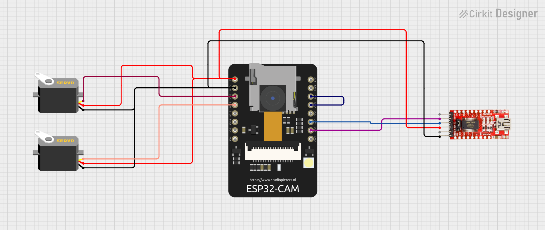
This document provides a detailed overview of a circuit involving an ESP32 CAM module, two servo motors, and an FTDI programmer. The ESP32 CAM is used to control the servo motors, and the FTDI programmer is used for programming the ESP32 CAM. The circuit is powered through the FTDI programmer.
Component List
ESP32 CAM
- Description: A microcontroller with integrated Wi-Fi and Bluetooth, equipped with a camera module.
- Pins: 5V, GND, GPIO12, GPIO13, GPIO15, GPIO14, GPIO2, GPIO4, 3.3V, GPIO16, GPIO0, 3.3V / 5V / P_OUT, GPIO3 / RX, GPIO1 / TX
Servo (1)
- Description: A servo motor used for precise control of angular position.
- Pins: gnd, vcc, pulse
Servo (2)
- Description: Another servo motor used for precise control of angular position.
- Pins: gnd, vcc, pulse
FTDI Programmer
- Description: A USB-to-serial adapter used for programming the ESP32 CAM.
- Pins: DTR, RX, TX, VCC, CTS, GND
Wiring Details
ESP32 CAM
- 5V: Connected to VCC of FTDI Programmer, vcc of Servo (1), and vcc of Servo (2)
- GND: Connected to GND of FTDI Programmer, gnd of Servo (1), and gnd of Servo (2)
- GPIO12: Connected to pulse of Servo (1)
- GPIO13: Connected to pulse of Servo (2)
- GPIO0: Connected to GND of ESP32 CAM
- GPIO3 / RX: Connected to TX of FTDI Programmer
- GPIO1 / TX: Connected to RX of FTDI Programmer
Servo (1)
- gnd: Connected to GND of FTDI Programmer, GND of ESP32 CAM, and gnd of Servo (2)
- vcc: Connected to VCC of FTDI Programmer, 5V of ESP32 CAM, and vcc of Servo (2)
- pulse: Connected to GPIO12 of ESP32 CAM
Servo (2)
- gnd: Connected to GND of FTDI Programmer, GND of ESP32 CAM, and gnd of Servo (1)
- vcc: Connected to VCC of FTDI Programmer, 5V of ESP32 CAM, and vcc of Servo (1)
- pulse: Connected to GPIO13 of ESP32 CAM
FTDI Programmer
- VCC: Connected to 5V of ESP32 CAM, vcc of Servo (1), and vcc of Servo (2)
- GND: Connected to GND of ESP32 CAM, gnd of Servo (1), and gnd of Servo (2)
- TX: Connected to GPIO3 / RX of ESP32 CAM
- RX: Connected to GPIO1 / TX of ESP32 CAM
Code
No code is provided for this circuit.