
Arduino UNO Based Rain Detection System with Alert Indicators
View and Edit Project In Cirkit Designer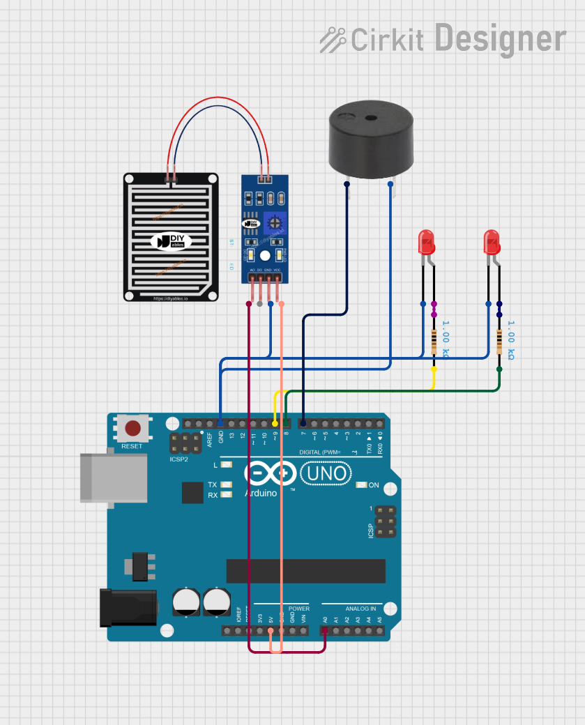
Circuit Documentation
Summary
This circuit is designed to monitor environmental conditions using a rain sensor and provide visual and audible alerts based on the sensor's readings. The core of the circuit is an Arduino UNO microcontroller, which processes the sensor data and controls two LEDs (red) and a buzzer. The rain sensor's analog output is connected to the Arduino's analog input for monitoring. Depending on the sensor's output, the Arduino activates or deactivates the LEDs and the buzzer to indicate the presence of rain.
Component List
RAIN SENSOR
- Pins: AO (Analog Output), DO (Digital Output), GRD (Ground), VCC (Power Supply)
- Description: A sensor that detects rain by measuring the resistance between two traces.
Arduino UNO
- Pins: IOREF, Reset, 3.3V, 5V, GND, Vin, A0-A5, SCL, SDA, AREF, D0-D13
- Description: A microcontroller board based on the ATmega328P, widely used for prototyping and educational purposes.
LED: Two Pin (red)
- Pins: cathode, anode
- Description: A red light-emitting diode that emits light when a forward current passes through it.
Resistor
- Pins: pin1, pin2
- Description: A passive two-terminal electrical component that implements electrical resistance as a circuit element.
- Properties: Resistance: 1000 Ohms
Buzzer
- Pins: PIN, GND
- Description: An audio signaling device that can be mechanical, electromechanical, or piezoelectric.
Wiring Details
RAIN SENSOR
- AO connected to Arduino UNO A0
- GRD connected to Arduino UNO GND
- VCC connected to Arduino UNO 5V
Arduino UNO
- A0 connected to RAIN SENSOR AO
- GND connected to RAIN SENSOR GRD, LED cathodes, and buzzer GND
- 5V connected to RAIN SENSOR VCC
- D9 connected to Resistor (pin2)
- D8 connected to Resistor (pin2)
- D7 connected to Buzzer PIN
LED: Two Pin (red)
- cathode connected to Arduino UNO GND
- anode connected to Resistor (pin1)
Resistor
- pin1 connected to LED anode
- pin2 connected to Arduino UNO D9 or D8
Buzzer
- PIN connected to Arduino UNO D7
- GND connected to Arduino UNO GND
Documented Code
// Define sensor and output pins
int sensorPin = A0;
int greenLed = 8;
int blueLed = 9;
int buzzer = 7;

// Setup function to initialize pins
void setup() {
  pinMode(greenLed, OUTPUT);
  pinMode(blueLed, OUTPUT);
  pinMode(buzzer, OUTPUT);
  Serial.begin(9600);
}

// Main loop function
void loop() {
  // Read the value from the rain sensor
  int sensorValue = analogRead(sensorPin);
  Serial.println(sensorValue);

  // If the sensor value is greater than 500
  if (sensorValue > 500) {
    // Rain detected: turn on blue LED and buzzer, turn off green LED
    digitalWrite(blueLed, HIGH);
    digitalWrite(greenLed, LOW);
    digitalWrite(buzzer, HIGH);
  } else {
    // No rain detected: turn on green LED, turn off blue LED and buzzer
    digitalWrite(blueLed, LOW);
    digitalWrite(greenLed, HIGH);
    digitalWrite(buzzer, LOW);
  }

  // Wait for half a second
  delay(500);
}
The code is written for the Arduino UNO microcontroller. It initializes the pins connected to the LEDs and the buzzer as outputs and sets up serial communication. In the main loop, the rain sensor's analog value is read and printed to the serial monitor. If the value exceeds a threshold (500), indicating rain, the blue LED and buzzer are activated, and the green LED is deactivated. If the value is below the threshold, the green LED is activated, and the blue LED and buzzer are deactivated. The loop then pauses for 500 milliseconds before repeating.