
Arduino Uno Wi-Fi Controlled Rover with Ultrasonic and PIR Sensors
View and Edit Project In Cirkit Designer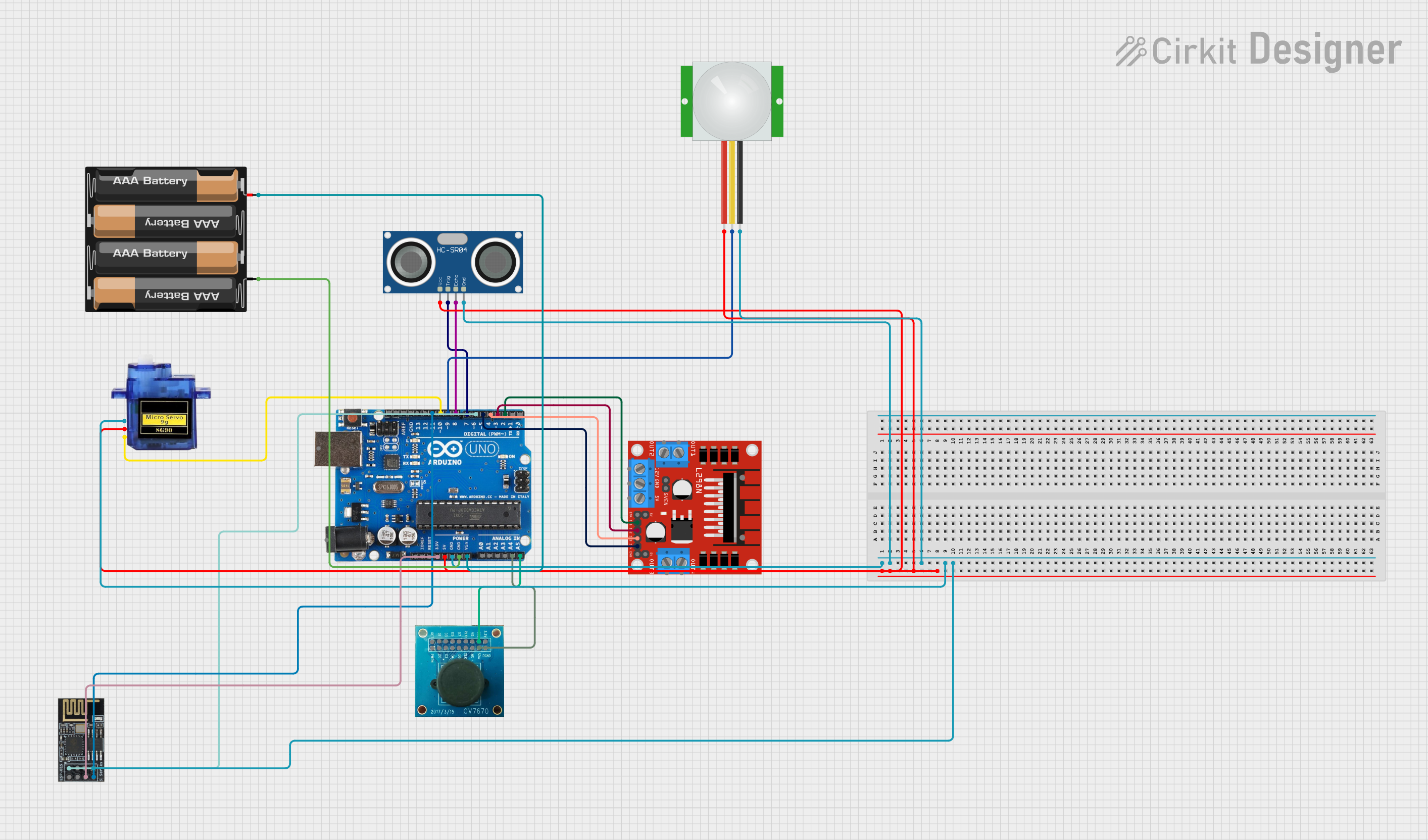
Circuit Documentation
Summary
This circuit is designed to control a rover with various sensors and actuators using an Arduino Uno R3. The rover can be controlled via a web interface over Wi-Fi, and it includes functionalities such as motion detection, distance measurement, and camera panning.
Component List
Arduino Uno R3
- Description: A microcontroller board based on the ATmega328P.
- Pins: D8, D9, D10, D11, D12, D13, GND, AREF, SDA, SCL, D0/RX, D1/Tx, D2, D3, D4, D5, 6, D7, A5/SCL, A4/SDA, A3, A2, A1, A0, Vin, 5V, 3.3V, RESET, IOREF, NONE, USB Jack, Power Jack
HC-SR04 Ultrasonic Sensor
- Description: A sensor used for distance measurement.
- Pins: VCC, TRIG, ECHO, GND
PIR Sensor
- Description: A sensor used for motion detection.
- Pins: VDD, SIG, GND
Micro Servo 9G
- Description: A small servo motor used for camera panning.
- Pins: GND, +5V, PWM
L298N DC Motor Driver
- Description: A dual H-Bridge motor driver used to control the motors of the rover.
- Pins: OUT1, OUT2, 12V, GND, 5V, OUT3, OUT4, 5V-ENA-JMP-I, 5V-ENA-JMP-O, +5V-J1, +5V-J2, ENA, IN1, IN2, IN3, IN4, ENB
WiFi Module ESP8266-01
- Description: A Wi-Fi module used for wireless communication.
- Pins: RX, GPIO0, GPIO2, GND, +3V3, Reset, CH-PD Chip power down, TX
OV7670 Camera Module
- Description: A camera module used for capturing images.
- Pins: RET, PWDN, D1, D0, D3, D2, D4, D5, D6, PLK, XLK, D7, VS, HS, SCL, SDA, 3.3V, DGND
4 x AAA Battery Mount
- Description: A battery holder for four AAA batteries.
- Pins: -, +
Wiring Details
Arduino Uno R3
- D8: Connected to ECHO pin of HC-SR04 Ultrasonic Sensor
- D9: Connected to SIG pin of PIR Sensor
- D10: Connected to PWM pin of Micro Servo 9G
- D11: Connected to TX pin of WiFi Module ESP8266-01
- D2: Connected to IN1 pin of L298N DC Motor Driver
- D3: Connected to IN2 pin of L298N DC Motor Driver
- D4: Connected to IN3 pin of L298N DC Motor Driver
- D5: Connected to IN4 pin of L298N DC Motor Driver
- 6: Connected to RX pin of WiFi Module ESP8266-01
- D7: Connected to TRIG pin of HC-SR04 Ultrasonic Sensor
- A5/SCL: Connected to SCL pin of OV7670 Camera Module
- A4/SDA: Connected to SDA pin of OV7670 Camera Module
- Vin: Connected to + pin of 4 x AAA Battery Mount
- GND: Connected to - pin of 4 x AAA Battery Mount, GND pin of HC-SR04 Ultrasonic Sensor, GND pin of PIR Sensor, GND pin of Micro Servo 9G, GND pin of WiFi Module ESP8266-01
- 5V: Connected to VCC pin of HC-SR04 Ultrasonic Sensor, VDD pin of PIR Sensor, +5V pin of Micro Servo 9G
- 3.3V: Connected to CH-PD Chip power down pin of WiFi Module ESP8266-01
HC-SR04 Ultrasonic Sensor
- VCC: Connected to 5V pin of Arduino Uno R3
- TRIG: Connected to D7 pin of Arduino Uno R3
- ECHO: Connected to D8 pin of Arduino Uno R3
- GND: Connected to GND pin of Arduino Uno R3
PIR Sensor
- VDD: Connected to 5V pin of Arduino Uno R3
- SIG: Connected to D9 pin of Arduino Uno R3
- GND: Connected to GND pin of Arduino Uno R3
Micro Servo 9G
- GND: Connected to GND pin of Arduino Uno R3
- +5V: Connected to 5V pin of Arduino Uno R3
- PWM: Connected to D10 pin of Arduino Uno R3
L298N DC Motor Driver
- IN1: Connected to D2 pin of Arduino Uno R3
- IN2: Connected to D3 pin of Arduino Uno R3
- IN3: Connected to D4 pin of Arduino Uno R3
- IN4: Connected to D5 pin of Arduino Uno R3
WiFi Module ESP8266-01
- RX: Connected to 6 pin of Arduino Uno R3
- TX: Connected to D11 pin of Arduino Uno R3
- GND: Connected to GND pin of Arduino Uno R3
- CH-PD Chip power down: Connected to 3.3V pin of Arduino Uno R3
OV7670 Camera Module
- SCL: Connected to A5/SCL pin of Arduino Uno R3
- SDA: Connected to A4/SDA pin of Arduino Uno R3
4 x AAA Battery Mount
- +: Connected to Vin pin of Arduino Uno R3
- -: Connected to GND pin of Arduino Uno R3
Code Documentation
#include <ESP8266WiFi.h>
#include <Servo.h>

// Define Wi-Fi credentials
const char* ssid = "YourWiFiSSID";
const char* password = "YourWiFiPassword";

// Define pin connections
const int motorA1 = D2;
const int motorA2 = D3;
const int motorB1 = D4;
const int motorB2 = D5;
const int servoPin = D10;  // Servo motor for camera panning
const int trigPin = D7;    // HC-SR04 Trigger Pin
const int echoPin = D8;    // HC-SR04 Echo Pin
const int pirPin = D9;     // PIR sensor Pin

Servo cameraServo;  // Create Servo object

WiFiServer server(80);  // HTTP server on port 80

void setup() {
  // Start serial communication for debugging
  Serial.begin(115200);

  // Initialize the motor control pins
  pinMode(motorA1, OUTPUT);
  pinMode(motorA2, OUTPUT);
  pinMode(motorB1, OUTPUT);
  pinMode(motorB2, OUTPUT);

  // Initialize the servo motor for camera panning
  cameraServo.attach(servoPin);
  cameraServo.write(90);  // Set initial position to middle (90 degrees)

  // Initialize the HC-SR04 ultrasonic sensor
  pinMode(trigPin, OUTPUT);
  pinMode(echoPin, INPUT);

  // Initialize PIR sensor
  pinMode(pirPin, INPUT);

  // Connect to Wi-Fi
  WiFi.begin(ssid, password);
  while (WiFi.status() != WL_CONNECTED) {
    delay(1000);
    Serial.println("Connecting to WiFi...");
  }
  Serial.println("WiFi connected!");

  // Start the server
  server.begin();
  Serial.println("Server started");
}

void loop() {
  // Check for incoming clients (Web browser connection)
  WiFiClient client = server.available();
  if (client) {
    String request = client.readStringUntil('\r');
    client.flush();

    // Print out the received request (for debugging)
    Serial.println(request);

    // Control the rover based on the HTTP request
    if (request.indexOf("/forward") != -1) {
      moveForward();
    }
    else if (request.indexOf("/backward") != -1) {
      moveBackward();
    }
    else if (request.indexOf("/left") != -1) {
      moveLeft();
    }
    else if (request