
Circuit Documentation
Summary
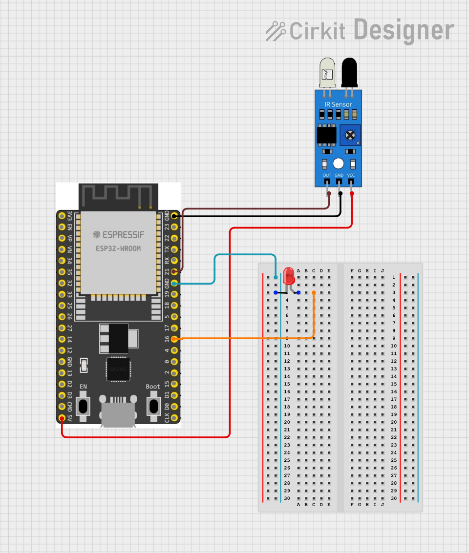
This document provides a detailed description of a circuit that includes an ESP32 Wroom Dev Kit, an IR sensor, and a red LED. The ESP32 microcontroller interfaces with the IR sensor to detect infrared signals and controls the LED based on the sensor's output.
Component List
ESP32 Wroom Dev Kit
- Description: A powerful microcontroller with integrated Wi-Fi and Bluetooth capabilities.
- Pins: NOP, EN, VP, VN, GPIO 34, GPIO 35, GPIO 32, GPIO 33, GPIO 25, GPIO 26, GPIO 27, GPIO 14, GPIO 13, V5, GPIO 23, GPIO 22, TXD, RXD, GPIO 21, GND, GPIO 19, GPIO 18, GPIO 5, GPIO 17, GPIO 16, GPIO 4, GPIO 0, GPIO 15, 3V3
IR Sensor
- Description: An infrared sensor used to detect IR signals.
- Pins: out, gnd, vcc
LED: Two Pin (Red)
- Description: A standard red LED.
- Pins: cathode, anode
Wiring Details
ESP32 Wroom Dev Kit
- GPIO 21 is connected to out of the IR sensor.
- NOP is connected to gnd of the IR sensor.
- V5 is connected to vcc of the IR sensor.
- GND is connected to cathode of the LED.
- GPIO 16 is connected to anode of the LED.
IR Sensor
- out is connected to GPIO 21 of the ESP32 Wroom Dev Kit.
- gnd is connected to NOP of the ESP32 Wroom Dev Kit.
- vcc is connected to V5 of the ESP32 Wroom Dev Kit.
LED: Two Pin (Red)
- cathode is connected to GND of the ESP32 Wroom Dev Kit.
- anode is connected to GPIO 16 of the ESP32 Wroom Dev Kit.
Code
There is no code provided for this circuit.