
Arduino Nano-Based Wireless Ignition System with LCD Display and nRF24L01
View and Edit Project In Cirkit Designer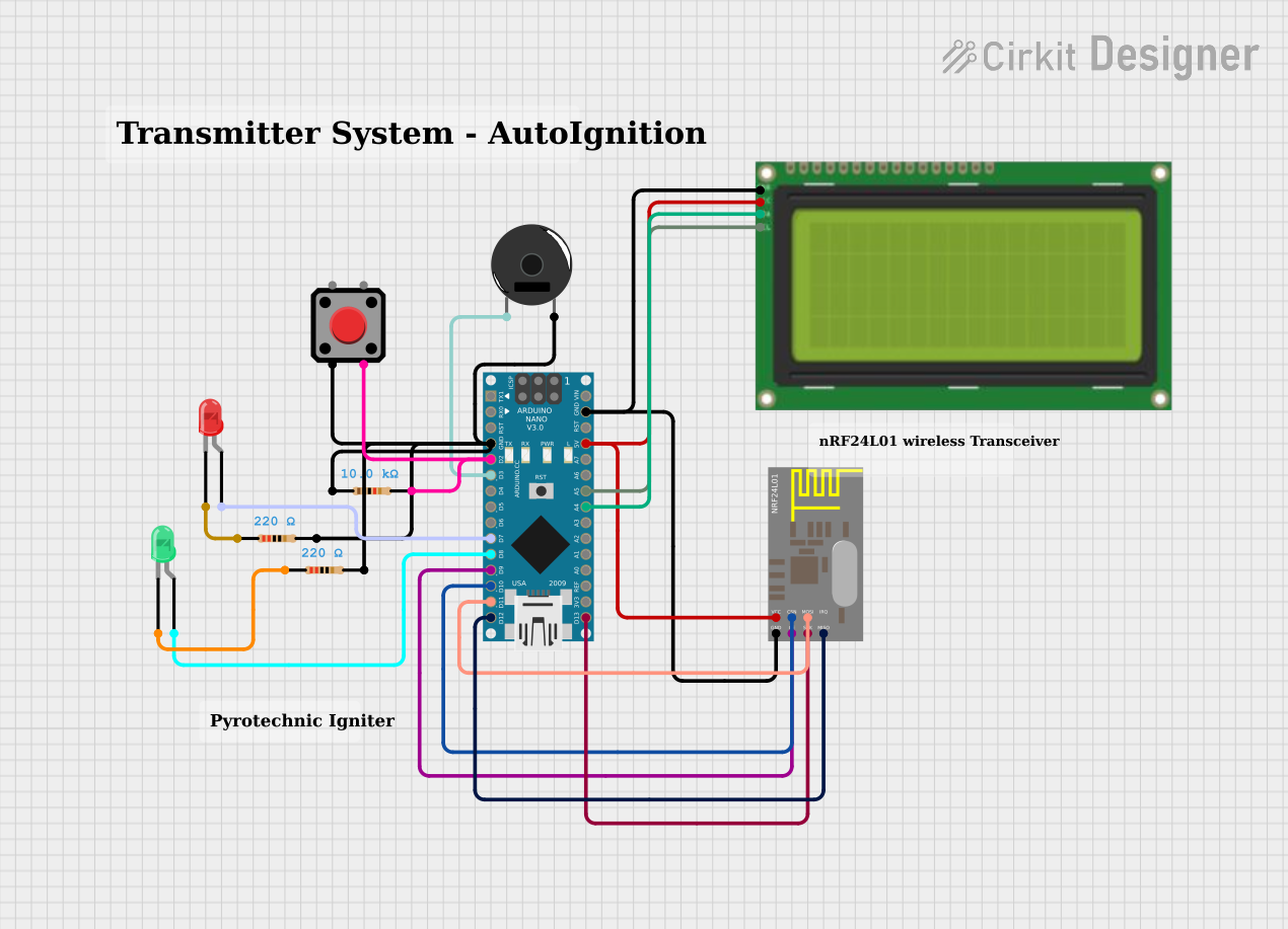
Circuit Documentation
Summary
This circuit is designed to control an ignition sequence using an Arduino Nano. The system includes a pushbutton to start the ignition, a piezo buzzer and an LED for feedback, an nRF24L01 module for wireless communication, and an LCD display for status messages. The circuit also includes resistors to limit current to the LEDs and pushbutton.
Component List
Arduino Nano
- Description: A small, complete, and breadboard-friendly board based on the ATmega328P.
- Pins: D1/TX, D0/RX, RESET, GND, D2, D3, D4, D5, D6, D7, D8, D9, D10, D11/MOSI, D12/MISO, VIN, 5V, A7, A6, A5, A4, A3, A2, A1, A0, AREF, 3V3, D13/SCK
Red Pushbutton
- Description: A simple pushbutton switch.
- Pins: Pin 2, Pin 1, Pin 3, Pin 4
nRF24L01
- Description: A wireless transceiver module.
- Pins: GND, VCC, CE, CSN, SCK, MOSI, MISO, IRQ
Piezo Buzzer
- Description: A small buzzer for audio feedback.
- Pins: pin 1, pin 2
Lcd 20x4 i2c
- Description: A 20x4 character LCD display with I2C interface.
- Pins: GND, 5v, SCA, SCL
LED: Two Pin (red)
- Description: A red LED.
- Pins: cathode, anode
Resistor (10k Ohms)
- Description: A resistor with a resistance of 10k Ohms.
- Pins: pin1, pin2
LED: Two Pin (green)
- Description: A green LED.
- Pins: cathode, anode
Resistor (220 Ohms)
- Description: A resistor with a resistance of 220 Ohms.
- Pins: pin1, pin2
Wiring Details
Arduino Nano
- GND: Connected to GND of Red Pushbutton, Piezo Buzzer, Resistor (10k Ohms), nRF24L01, and Lcd 20x4 i2c.
- D2: Connected to Pin 3 of Red Pushbutton and pin2 of Resistor (10k Ohms).
- D3: Connected to pin 1 of Piezo Buzzer.
- D7: Connected to anode of Red LED.
- D8: Connected to anode of Green LED.
- D9: Connected to CE of nRF24L01.
- D10: Connected to CSN of nRF24L01.
- D11/MOSI: Connected to MOSI of nRF24L01.
- D12/MISO: Connected to MISO of nRF24L01.
- 5V: Connected to 5v of Lcd 20x4 i2c and VCC of nRF24L01.
- A5: Connected to SCL of Lcd 20x4 i2c.
- A4: Connected to SCA of Lcd 20x4 i2c.
- D13/SCK: Connected to SCK of nRF24L01.
Red Pushbutton
- Pin 2: Connected to pin 2 of Piezo Buzzer, pin2 of Resistor (220 Ohms), pin2 of Resistor (220 Ohms), GND of Arduino Nano, and pin1 of Resistor (10k Ohms).
- Pin 3: Connected to D2 of Arduino Nano and pin2 of Resistor (10k Ohms).
Piezo Buzzer
- pin 1: Connected to D3 of Arduino Nano.
- pin 2: Connected to Pin 2 of Red Pushbutton.
Lcd 20x4 i2c
- GND: Connected to GND of nRF24L01 and GND of Arduino Nano.
- 5v: Connected to 5V of Arduino Nano and VCC of nRF24L01.
- SCL: Connected to A5 of Arduino Nano.
- SCA: Connected to A4 of Arduino Nano.
LED: Two Pin (red)
- anode: Connected to D7 of Arduino Nano.
- cathode: Connected to pin1 of Resistor (220 Ohms).
LED: Two Pin (green)
- anode: Connected to D8 of Arduino Nano.
- cathode: Connected to pin1 of Resistor (220 Ohms).
nRF24L01
- CE: Connected to D9 of Arduino Nano.
- CSN: Connected to D10 of Arduino Nano.
- MOSI: Connected to D11/MOSI of Arduino Nano.
- MISO: Connected to D12/MISO of Arduino Nano.
- SCK: Connected to D13/SCK of Arduino Nano.
- GND: Connected to GND of Lcd 20x4 i2c and GND of Arduino Nano.
- VCC: Connected to 5V of Arduino Nano and 5v of Lcd 20x4 i2c.
Resistor (10k Ohms)
- pin1: Connected to GND of Arduino Nano.
- pin2: Connected to Pin 3 of Red Pushbutton and D2 of Arduino Nano.
Resistor (220 Ohms)
- pin1: Connected to cathode of Red LED.
- pin2: Connected to Pin 2 of Red Pushbutton.
Resistor (220 Ohms)
- pin1: Connected to cathode of Green LED.
- pin2: Connected to Pin 2 of Red Pushbutton.
Code Documentation
// Include libraries
#include <Wire.h>
#include <LiquidCrystal_I2C.h>
#include <SPI.h>
#include <nRF24L01.h>
#include <RF24.h>

// Define Pins
#define BUTTON_PIN 2         // Push Button pin
#define BUZZER_PIN 6         // Buzzer pin
#define LED_PIN 7            // LED pin

// Initialize LCD (20x4 with I2C)
LiquidCrystal_I2C lcd(0x27, 20, 4);  // I2C address 0x27, 20 columns, 4 rows

// Initialize nRF24L01 Radio (Transmitter)
RF24 radio(9, 10);  // CE Pin 9, CSN Pin 10
const byte address[6] = "00001";  // Address for communication

// Define Variables
bool ignitionSequenceStarted = false;

void setup() {
  // Initialize Serial Monitor
  Serial.begin(9600);

  // Initialize LCD
  lcd.begin(16, 2);
  lcd.backlight();

  // Initialize Buzzer and LED
  pinMode(BUZZER_PIN, OUTPUT);
  pinMode(LED_PIN, OUTPUT);

  // Initialize Button
  pinMode(BUTTON_PIN, INPUT_PULLUP);  // Internal pull-up resistor

  // Initialize nRF24L01 Radio
  radio.begin();
  radio.openWritingPipe(address);  // Set the transmitter address
  radio.setPALevel(RF24_PA_HIGH); // Set Power Amplifier level

  // Display welcome message on LCD
  lcd.setCursor(0, 0);
  lcd.print("System Ready");
  delay(1000);
  lcd.clear();
}

void loop() {
  // Check if the button is pressed
  if (digitalRead(BUTTON_PIN) == LOW) {  // Button pressed (active LOW)
    if (!ignitionSequenceStarted) {
      ignitionSequenceStarted = true;

      // Display message on LCD
      lcd.setCursor(0, 0);
      lcd.print("Ignition Started");

      // Activate Buzzer and LED as feedback
      digitalWrite(BUZZER_PIN, HIGH);
      digitalWrite(LED_PIN, HIGH);

      // Send ignition signal wirelessly
      sendIgnitionSignal();

      // Delay for 1 second to simulate the ignition process
      delay(1000);

      // Turn off Buzzer and LED
      digitalWrite(BUZZER_PIN, LOW);
      digitalWrite(LED_PIN, LOW);

      // Display success message on LCD
      lcd.clear();
      lcd.setCursor(0, 0);
      lcd.print("Ignition Complete");
      delay(1000);  // Show message for 1 second
      lcd.clear();

      // Reset for next ignition sequence
      ignitionSequenceStarted = false;
    }
  }
}

void sendIgnitionSignal() {
  // Send a signal through nRF24L01
  char signal[] = "IGNITE";  // Message to indicate ignition

  if (radio.write(&signal, sizeof(signal))) {
    Serial.println("