
ESP32-Based RJ45 Cable Tester with LED Indicators and Buzzer
View and Edit Project In Cirkit Designer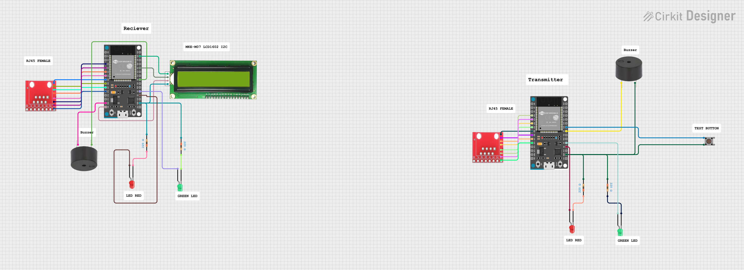
Circuit Documentation
Summary
This circuit involves an ESP32 microcontroller interfacing with various components including LEDs, resistors, a buzzer, an LCD display, an RJ45 connector, and a pushbutton. The circuit is designed to test the continuity and measure the length of cables connected to the RJ45 connector. The ESP32 controls the LEDs and buzzer to indicate the status of the test, and the results are displayed on the LCD.
Component List
LED: Two Pin (green)
- Pins: cathode, anode
- Description: Green LED used for visual indication.
LED: Two Pin (red)
- Pins: cathode, anode
- Description: Red LED used for visual indication.
Resistor
- Pins: pin1, pin2
- Description: 220 Ohms resistor used for current limiting.
- Properties:
- Resistance: 220 Ohms
buzzer
- Pins: PIN, GND
- Description: Buzzer used for audible indication.
ESP32 Devkit V1
- Pins: 3V3, GND, D15, D2, D4, RX2, TX2, D5, D18, D19, D21, RX0, TX0, D22, D23, EN, VP, VN, D34, D35, D32, D33, D25, D26, D27, D14, D12, D13, VIN
- Description: Microcontroller used to control the circuit.
RJ45
- Pins: R1+, R1-, R2+, R2-, R3+, R3-, 5V, GND
- Description: RJ45 connector used for cable testing.
MKE-M07 LCD1602 I2C
- Pins: GND, 5V, SDA, SCL
- Description: LCD display used to show test results.
Pushbutton
- Pins: Pin 3 (out), Pin 4 (out), Pin 1 (in), Pin 2 (in)
- Description: Pushbutton used to initiate the test.
Wiring Details
LED: Two Pin (green)
- Anode connected to ESP32 Devkit V1 pin D4
- Cathode connected to Resistor pin pin2
LED: Two Pin (red)
- Anode connected to ESP32 Devkit V1 pin D2
- Cathode connected to Resistor pin pin1
Resistor (220 Ohms)
- Pin1 connected to LED: Two Pin (red) pin cathode
- Pin2 connected to LED: Two Pin (green) pin cathode
Resistor (220 Ohms)
- Pin1 connected to Resistor pin pin2
- Pin2 connected to ESP32 Devkit V1 pin GND
buzzer
- PIN connected to ESP32 Devkit V1 pin D5
- GND connected to ESP32 Devkit V1 pin GND
ESP32 Devkit V1
- GND connected to Resistor pin pin2
- D2 connected to LED: Two Pin (red) pin anode
- D4 connected to LED: Two Pin (green) pin anode
- D5 connected to buzzer pin PIN
- D21 connected to MKE-M07 LCD1602 I2C pin SDA
- D22 connected to MKE-M07 LCD1602 I2C pin SCL
- D25 connected to RJ45 pin R1+
- D26 connected to RJ45 pin R1-
- D27 connected to RJ45 pin R2+
- D32 connected to RJ45 pin R2-
- D33 connected to RJ45 pin R3+
- D34 connected to RJ45 pin R3-
- D35 connected to RJ45 pin 5V
- VIN connected to MKE-M07 LCD1602 I2C pin 5V
RJ45
- R1+ connected to ESP32 Devkit V1 pin D25
- R1- connected to ESP32 Devkit V1 pin D26
- R2+ connected to ESP32 Devkit V1 pin D27
- R2- connected to ESP32 Devkit V1 pin D32
- R3+ connected to ESP32 Devkit V1 pin D33
- R3- connected to ESP32 Devkit V1 pin D34
- 5V connected to ESP32 Devkit V1 pin D35
- GND connected to ESP32 Devkit V1 pin D14
MKE-M07 LCD1602 I2C
- GND connected to Resistor pin pin2
- 5V connected to ESP32 Devkit V1 pin VIN
- SDA connected to ESP32 Devkit V1 pin D21
- SCL connected to ESP32 Devkit V1 pin D22
Pushbutton
- Pin 2 (in) connected to ESP32 Devkit V1 pin D18
- Pin 4 (out) connected to Resistor pin pin2
Code Documentation
Code for ESP32 Devkit V1 (Instance 1)
#include <Wire.h>
#include <LiquidCrystal_I2C.h>

// Define the GPIO pins connected to the Female RJ45
const int female_rj45_pins[8] = {25, 26, 27, 32, 33, 34, 35, 14};

// Define the GPIO pins for the LEDs
const int greenLED = 2;
const int redLED = 4;

// Define the GPIO pin for the buzzer
const int buzzerPin = 5;

// Create an LCD object connected to I2C (address 0x27)
LiquidCrystal_I2C lcd(0x27, 16, 2);

// Speed of signal in wire (in meters per microsecond)
const float signalSpeed = 0.0343;

// Wire colors
const char* wireColors[8] = {
  "Orange/White",
  "Orange",
  "Green/White",
  "Blue",
  "Blue/White",
  "Green",
  "Brown/White",
  "Brown"
};

void setup() {
  Serial.begin(115200);

  // Initialize the LCD
  lcd.init();
  lcd.backlight();
  lcd.clear();

  // Initialize the GPIO pins for Female RJ45
  for (int i = 0; i < 8; i++) {
    pinMode(female_rj45_pins[i], INPUT_PULLUP);
  }

  // Initialize the GPIO pins for LEDs
  pinMode(greenLED, OUTPUT);
  pinMode(redLED, OUTPUT);
  digitalWrite(greenLED, LOW);
  digitalWrite(redLED, LOW);

  // Initialize the GPIO pin for the buzzer
  pinMode(buzzerPin, OUTPUT);
  digitalWrite(buzzerPin, LOW);
}

void loop() {
  // Start the test
  runTest();
  delay(1000); // Delay for readability
}

void runTest() {
  bool allConnected = true;
  lcd.clear();

  // Continuity Testing for Female RJ45
  for (int i = 0; i < 8; i++) {
    int state = digitalRead(female_rj45_pins[i]);
    if (state == HIGH) {
      Serial.print("Female Wire ");
      Serial.print(i + 1);
      Serial.print(" (");
      Serial.print(wireColors[i]);
      Serial.println(") is connected.");
    } else {
      Serial.print("Female Wire ");
      Serial.print(i + 1);
      Serial.print(" (");
      Serial.print(wireColors[i]);
      Serial.println(") is not connected.");
      lcd.setCursor(0, i % 2);
      lcd.print(wireColors[i]);
      lcd.print(" not conn");
      allConnected = false;
    }
  }

  // Distance Measurement
  if (allConnected) {
    lcd.setCursor(0, 0);
    lcd.print("All wires conn");
    lcd.setCursor(0, 1);
    lcd.print("Length: ");
    lcd.print(measureLength());
    lcd.print(" m");

    // Indicate success
    digitalWrite(greenLED, HIGH);
    digitalWrite(buzzerPin, HIGH);
    delay(100);
    digitalWrite(buzzerPin, LOW);
    delay(100);
    digitalWrite(buzzerPin, HIGH);
    delay(100);
    digitalWrite(buzzerPin, LOW);
    digitalWrite(greenLED, LOW