Cirkit Designer
Your all-in-one circuit design IDE
Home /
Project Documentation
Arduino UNO Based Environmental Monitoring System with Wi-Fi Connectivity
Circuit Documentation
Summary of the Circuit
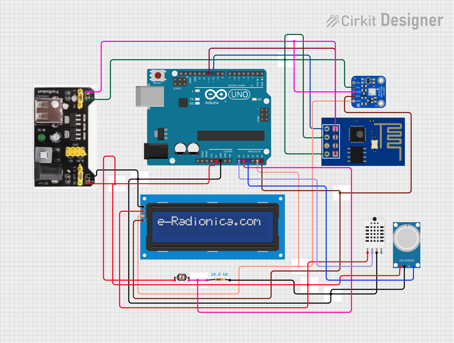
This circuit is designed to interface various sensors and modules with an Arduino UNO microcontroller. It includes a BMP180 barometric pressure sensor, an ESP-01 WiFi module, a photocell (LDR), a DHT03 humidity and temperature sensor, an MQ-4 methane gas sensor, and an LCD screen with I2C communication. The circuit is powered by an MB102 Breadboard Power Supply Module that provides both 3.3V and 5V outputs. A resistor is used in conjunction with the photocell to create a voltage divider for light intensity measurement. The Arduino UNO serves as the central processing unit, reading sensor data, and potentially sending data to the ESP-01 for WiFi communication.
Component List
Arduino UNO
- Microcontroller board based on the ATmega328P
- Provides digital and analog I/O pins
- Can be powered via USB or external power supply
Adafruit BMP180
- Barometric pressure sensor
- Can measure temperature as well
- Uses I2C communication
ESP-01
- WiFi module based on the ESP8266 chip
- Provides WiFi connectivity to the Arduino
- Communicates with the Arduino via serial (RX/TX)
Resistor
- Passive component used to limit current or divide voltage
- Resistance: 10,000 Ohms
Photocell (LDR)
- Light-dependent resistor
- Changes resistance based on the intensity of light
MB102 Breadboard Power Supply Module 3.3V/5V
- Provides both 3.3V and 5V outputs
- Powers the circuit components
LCD screen 16x2 I2C
- Alphanumeric liquid crystal display
- 16 characters by 2 lines
- Uses I2C communication for displaying data
Humidity and Temperature Sensor (DHT03)
- Measures ambient humidity and temperature
- Provides a digital signal output
MQ-4
- Methane gas sensor
- Provides both analog and digital outputs
Wiring Details
Arduino UNO
5Vconnected to the 5V power railGNDconnected to the ground railA0connected to the DHT03 data signalA1connected to one side of the photocell and to one side of the 10k resistor (forming a voltage divider)A2connected to the MQ-4 analog outputA4(SDA) connected to the I2C data lineA5(SCL) connected to the I2C clock lineD10connected to the ESP-01 TXD11connected to the ESP-01 RX
Adafruit BMP180
+3V3connected to the 3.3V power railGNDconnected to the ground railSCLconnected to the I2C clock lineSDAconnected to the I2C data line
ESP-01
VCCandCH_PDconnected to the 3.3V power railGNDconnected to the ground railRXconnected to Arduino UNO D11TXconnected to Arduino UNO D10
Resistor
- One side connected to the photocell
- The other side connected to the ground rail
Photocell (LDR)
- One side connected to the 5V power rail
- The other side connected to one side of the 10k resistor and to Arduino UNO A1
MB102 Breadboard Power Supply Module 3.3V/5V
3.3Voutput connected to the 3.3V power rail5voutput connected to the 5V power railGNDconnected to the ground rail
LCD screen 16x2 I2C
VCCconnected to the 5V power railGNDconnected to the ground railSCLconnected to the I2C clock lineSDAconnected to the I2C data line
Humidity and Temperature Sensor (DHT03)
Vccconnected to the 5V power railData-signalconnected to Arduino UNO A0GND 1connected to the ground rail
MQ-4
VCCconnected to the 5V power railGNDconnected to the ground railA0connected to Arduino UNO A2
Documented Code
Arduino UNO Code (sketch.ino)
void setup() {
  // put your setup code here, to run once:

}

void loop() {
  // put your main code here, to run repeatedly:

}
Additional Documentation (documentation.txt)
No additional code documentation provided.