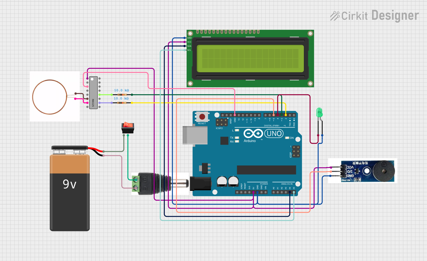
Arduino UNO Based Sensing Device with I2C LCD Feedback and Alert System

Circuit Documentation
Summary
This circuit is designed around an Arduino UNO microcontroller and includes various components such as an Active Buzzer Module, a green LED, a 16x2 I2C LCD, a copper coil, two resistors, a rocker switch, a 9V Battery, a 2.1mm Male connector, and an INA125 instrumentation amplifier. The Arduino UNO controls the buzzer and the LED, interfaces with the LCD via I2C communication, and interacts with the INA125 for signal conditioning purposes. The circuit is powered by a 9V battery, which is connected through a rocker switch.
Component List
Arduino UNO: A microcontroller board based on the ATmega328P. It has 14 digital input/output pins, 6 analog inputs, a 16 MHz quartz crystal, a USB connection, a power jack, an ICSP header, and a reset button.
Active Buzzer Module: An electronic device that produces a tone when provided with power.
LED (Green): A two-pin light-emitting diode that emits green light.
16x2 I2C LCD: A liquid crystal display capable of displaying 16 characters per line across 2 lines, with an I2C interface for communication.
Copper Coil: A coil of copper wire that can be used to create a magnetic field or to induce a voltage.
Resistor (10k Ohms): Two resistors with a resistance of 10,000 Ohms each, used for current limiting or voltage division.
Rocker Switch: A switch that allows current to flow when in the 'on' position and breaks the circuit when in the 'off' position.
9V Battery: A standard 9-volt battery used as the power source for the circuit.
2.1mm Male Connector: A male connector that matches the power jack on the Arduino UNO for supplying power.
INA125: An instrumentation amplifier with a precision voltage reference used for signal conditioning.
Wiring Details
Arduino UNO
- 5V: Connected to the VCC of the Active Buzzer Module, 16x2 I2C LCD, and V+ of the INA125.
- GND: Common ground connected to the GND of the Active Buzzer Module, 16x2 I2C LCD, and V- of the INA125. Also connected to the anode of the LED through a resistor.
- A4 (SDA): Connected to the SDA pin of the 16x2 I2C LCD for I2C communication.
- A5 (SCL): Connected to the SCL pin of the 16x2 I2C LCD for I2C communication.
- D5: Connected to the I/O pin of the Active Buzzer Module.
- D4: Connected to the cathode of the LED.
- D3: Connected to one end of a 10k Ohm resistor.
- D2: Connected to one end of another 10k Ohm resistor.
Active Buzzer Module
- VCC: Connected to the 5V output from the Arduino UNO.
- GND: Connected to the common ground.
- I/O: Controlled by the D5 pin of the Arduino UNO.
LED (Green)
- Anode: Connected to the common ground through a resistor.
- Cathode: Controlled by the D4 pin of the Arduino UNO.
16x2 I2C LCD
- VCC: Powered by the 5V output from the Arduino UNO.
- GND: Connected to the common ground.
- SDA: Receives data from the A4 pin of the Arduino UNO.
- SCL: Receives clock signal from the A5 pin of the Arduino UNO.
Copper Coil
- -ve: Connected to the V_in - of the INA125.
- +ve: Connected to the V_in + of the INA125.
Resistor (10k Ohms)
- One resistor has pin1 connected to the V_O of the INA125 and pin2 connected to the D2 pin of the Arduino UNO.
- The other resistor has pin1 connected to the V_REF OUT of the INA125 and pin2 connected to the D3 pin of the Arduino UNO.
Rocker Switch
- Input: Connected to the + pin of the 9V Battery.
- Output: Connected to the + pin of the 2.1mm Male Connector.
9V Battery
- +: Connected to the input of the Rocker Switch.
- -: Connected to the - pin of the 2.1mm Male Connector.
2.1mm Male Connector
- +: Receives power from the output of the Rocker Switch.
- -: Connected to the - pin of the 9V Battery.
INA125
- V+: Powered by the 5V output from the Arduino UNO.
- V-: Connected to the common ground.
- V_in +: Connected to the +ve of the copper coil.
- V_in -: Connected to the -ve of the copper coil.
- V_O: Connected to pin1 of one of the 10k Ohm resistors.
- V_REF OUT: Connected to pin1 of the other 10k Ohm resistor.
Documented Code
Arduino UNO Code (sketch.ino)
void setup() {
  // put your setup code here, to run once:

}

void loop() {
  // put your main code here, to run repeatedly:

}
Note: The provided code for the Arduino UNO is a template with empty setup and loop functions. The actual functionality needs to be implemented based on the requirements of the circuit's operation.