
Circuit Documentation
Summary of the Circuit
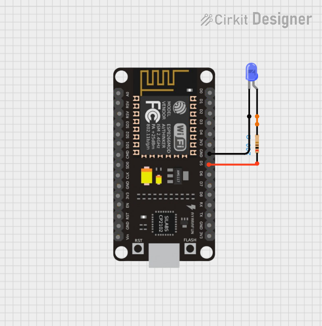
This circuit consists of an ESP8266 NodeMCU microcontroller, a blue LED, and a resistor. The purpose of the circuit is not explicitly stated, but based on the components and connections, it is likely designed to control the LED using one of the digital pins (D5) of the ESP8266 NodeMCU. The LED is connected in series with a resistor to limit the current flowing through the LED, protecting it from damage.
Component List
ESP8266 NodeMCU
- Description: A Wi-Fi capable microcontroller module based on the ESP8266 chip.
- Pins: D0, D1, D2, D3, D4, 3V3, GND, D5, D6, D7, D8, RX, TX, A0, RSV, SD3, SD2, SD1, CMD, SD0, CLK, EN, RST, VIN
LED: Two Pin (blue)
- Description: A standard blue light-emitting diode.
- Pins: cathode, anode
Resistor
- Description: A passive two-terminal electrical component that implements electrical resistance as a circuit element.
- Pins: pin1, pin2
- Resistance: 200 Ohms
Wiring Details
ESP8266 NodeMCU
- GND is connected to the cathode of the blue LED.
- D5 is connected to pin1 of the Resistor.
LED: Two Pin (blue)
- Cathode is connected to GND of the ESP8266 NodeMCU.
- Anode is connected to pin2 of the Resistor.
Resistor
- Pin1 is connected to D5 of the ESP8266 NodeMCU.
- Pin2 is connected to the anode of the blue LED.
Documented Code
There is no code provided for the microcontroller in this circuit. To control the LED, code would need to be written and uploaded to the ESP8266 NodeMCU to set pin D5 as an output and to toggle it high and low to turn the LED on and off, respectively. Since no code is provided, this section cannot be documented further.