ESP8266-Controlled Water Level Monitoring and Gate Management System

Circuit Documentation
Summary
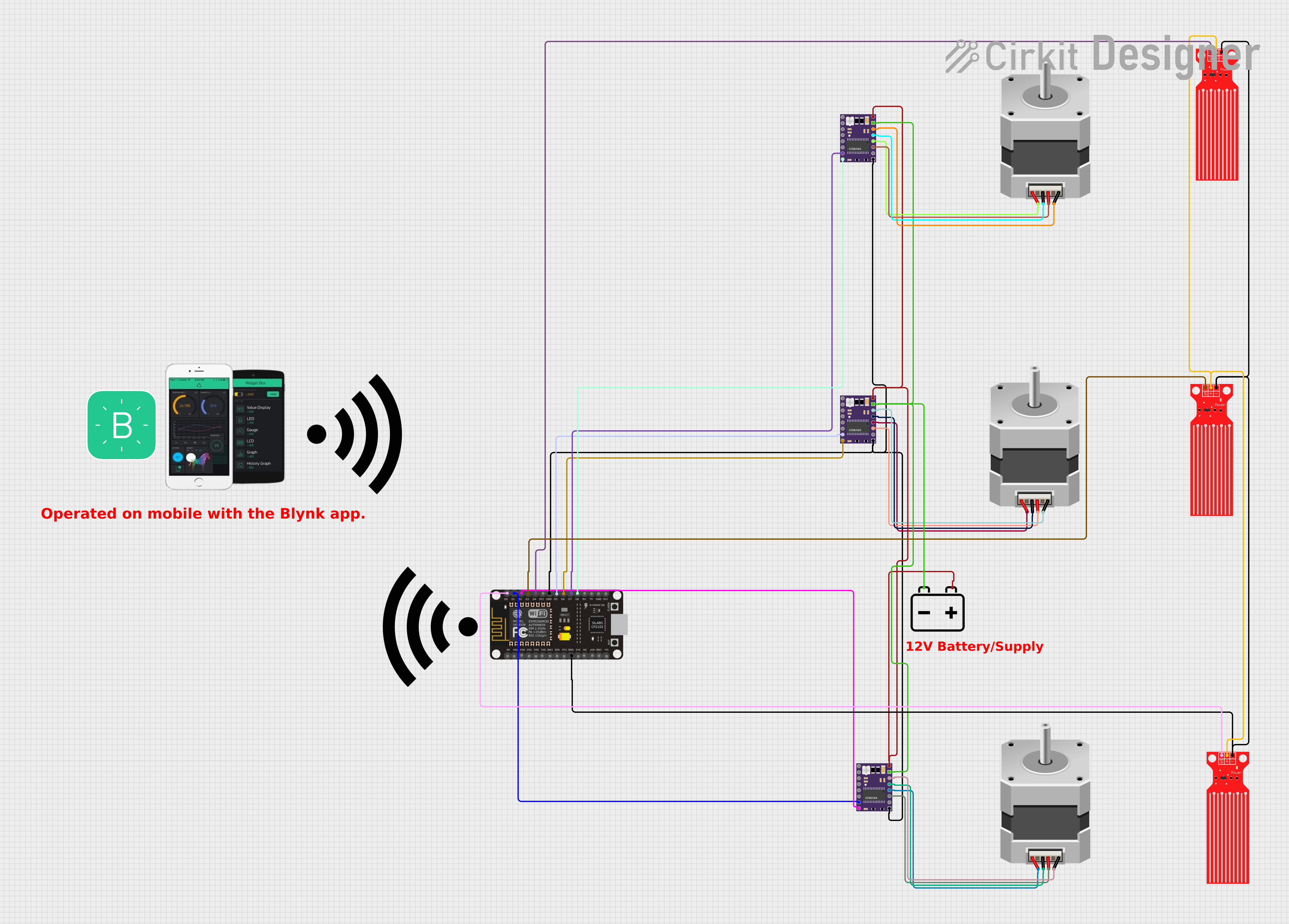
The circuit is designed to control two stepper motors using DRV8825 motor drivers and monitor water levels using three water level sensors. An ESP8266 NodeMCU microcontroller is used to interface with the components, read sensor data, and control the motors based on the water levels. The system can be manually controlled via the Blynk app, which communicates with the ESP8266 over WiFi. The circuit is powered by a 12V battery, which supplies power to the motor drivers and indirectly to the other components through the microcontroller's voltage regulator.
Component List
Water Level Sensor
- Description: A sensor that detects the presence of water.
- Pins: SIG (Signal), VCC (Power), GND (Ground).
Stepper Motor (Bipolar)
- Description: A bipolar stepper motor for precise motion control.
- Pins: D, B, C, A (Motor coil connections).
DRV 8825
- Description: A stepper motor driver capable of driving a bipolar stepper motor.
- Pins: EN (Enable), M0, M1, M2 (Microstepping Resolution), RST (Reset), SLP (Sleep), STEP (Step Control), DIR (Direction Control), VMOT (Motor Power Supply), GND MOTOR (Motor Ground), B2, B1, A1, A2 (Motor Coil Outputs), FAULT (Fault Output), GND LOGIC (Logic Ground).
12v Battery
- Description: A power source for the circuit.
- Pins: + (Positive), - (Negative).
ESP8266 NodeMCU
- Description: A WiFi-enabled microcontroller for IoT applications.
- Pins: D0-D8 (GPIO pins), RX, TX (Serial Communication), A0 (Analog Input), 3V3 (3.3V Power), GND (Ground), RST (Reset), EN (Enable), VIN (Voltage Input).
Wiring Details
Water Level Sensor
- SIG: Connected to ESP8266 NodeMCU GPIO pins (D0, D3, D4).
- VCC: Connected to a common power line (presumably 3.3V or 5V from the microcontroller).
- GND: Connected to the ESP8266 NodeMCU GND pin.
Stepper Motor (Bipolar)
- D, B, C, A: Connected to DRV8825 motor driver coil outputs (B2, A2, B1, A1).
DRV 8825
- STEP: Connected to ESP8266 NodeMCU GPIO pins (D1, D5, D7).
- DIR: Connected to ESP8266 NodeMCU GPIO pins (D2, D6, D8).
- VMOT: Connected to the 12v Battery positive terminal.
- GND MOTOR: Connected to the 12v Battery negative terminal.
- GND LOGIC: Connected to the ESP8266 NodeMCU GND pin.
- B2, B1, A1, A2: Connected to the corresponding pins on the stepper motors.
12v Battery
- +: Connected to DRV8825 VMOT pins.
- -: Connected to DRV8825 GND MOTOR pins.
Documented Code
#include <ESP8266WiFi.h>
#include <BlynkSimpleEsp8266.h>

// WiFi credentials
char ssid[] = "YourWiFiSSID";
char pass[] = "YourWiFiPassword";

// Blynk token
char auth[] = "YOUR_BLYNK_TOKEN";

// Motor driver pins
const int stepPin1 = D1; // DRV8825 Step pin for motor 1
const int dirPin1 = D2;  // DRV8825 Direction pin for motor 1
const int stepPin2 = D5; // DRV8825 Step pin for motor 2
const int dirPin2 = D6;  // DRV8825 Direction pin for motor 2

// Water level sensor pins
const int waterSensor1 = D3;
const int waterSensor2 = D4;

// Threshold for water level (LOW means water is below the sensor)
const int waterLevelThreshold = LOW;

// Blynk virtual pins
const int gateControlPin1 = V1; // Virtual pin for manual gate control 1
const int gateControlPin2 = V2; // Virtual pin for manual gate control 2

// Gate state
bool gateOpen1 = false;
bool gateOpen2 = false;

// Function to open gate (turn motor)
void openGate(int stepPin, int dirPin) {
  digitalWrite(dirPin, HIGH); // Set direction to open
  for (int i = 0; i < 200; i++) { // 200 steps as an example
    digitalWrite(stepPin, HIGH);
    delayMicroseconds(800); // Speed of the step (800us per step)
    digitalWrite(stepPin, LOW);
    delayMicroseconds(800);
  }
}

// Function to close gate (turn motor)
void closeGate(int stepPin, int dirPin) {
  digitalWrite(dirPin, LOW); // Set direction to close
  for (int i = 0; i < 200; i++) { // 200 steps as an example
    digitalWrite(stepPin, HIGH);
    delayMicroseconds(800); // Speed of the step (800us per step)
    digitalWrite(stepPin, LOW);
    delayMicroseconds(800);
  }
}

// Blynk function for manual gate control
BLYNK_WRITE(gateControlPin1) {
  gateOpen1 = param.asInt(); // Get value from Blynk app
  if (gateOpen1) {
    openGate(stepPin1, dirPin1);
  } else {
    closeGate(stepPin1, dirPin1);
  }
}

BLYNK_WRITE(gateControlPin2) {
  gateOpen2 = param.asInt(); // Get value from Blynk app
  if (gateOpen2) {
    openGate(stepPin2, dirPin2);
  } else {
    closeGate(stepPin2, dirPin2);
  }
}

void setup() {
  // Set motor pins as outputs
  pinMode(stepPin1, OUTPUT);
  pinMode(dirPin1, OUTPUT);
  pinMode(stepPin2, OUTPUT);
  pinMode(dirPin2, OUTPUT);

  // Set water level sensor pins as inputs
  pinMode(waterSensor1, INPUT);
  pinMode(waterSensor2, INPUT);

  // Start serial communication for debugging
  Serial.begin(9600);

  // Connect to WiFi
  WiFi.begin(ssid, pass);
  while (WiFi.status() != WL_CONNECTED) {
    delay(500);
    Serial.print(".");
  }
  Serial.println("WiFi connected");

  // Connect to Blynk
  Blynk.begin(auth, ssid, pass);
}

void loop() {
  Blynk.run(); // Run Blynk process

  // Read water level sensors
  int waterLevel1 = digitalRead(waterSensor1);
  int waterLevel2 = digitalRead(waterSensor2);

  // Automatic gate control based on water level
  if (waterLevel1 == waterLevelThreshold && !gateOpen1) {
    openGate(stepPin1, dirPin1);
    gateOpen1 = true;
  } else if (waterLevel1 != waterLevelThreshold && gateOpen1) {
    closeGate(stepPin1, dirPin1);
    gateOpen1 = false;
  }

  if (waterLevel2 == waterLevelThreshold && !gateOpen2) {
    openGate(stepPin2, dirPin2);
    gateOpen2 = true;
  } else if (waterLevel2 != waterLevelThreshold && gateOpen2) {
    closeGate(stepPin2, dirPin2);
    gateOpen2 = false;
  }
}
This code is designed to run on an ESP8266 NodeMCU microcontroller. It includes functionality to connect to a WiFi network, interface with the Blynk IoT platform, read water level sensors, and control stepper motors through DRV8825 drivers. The code provides both manual control via Blynk virtual pins and automatic control based on the water level sensors' readings.