
ESP32-Controlled Robotic Vehicle with Obstacle Detection and Alcohol Sensing
View and Edit Project In Cirkit Designer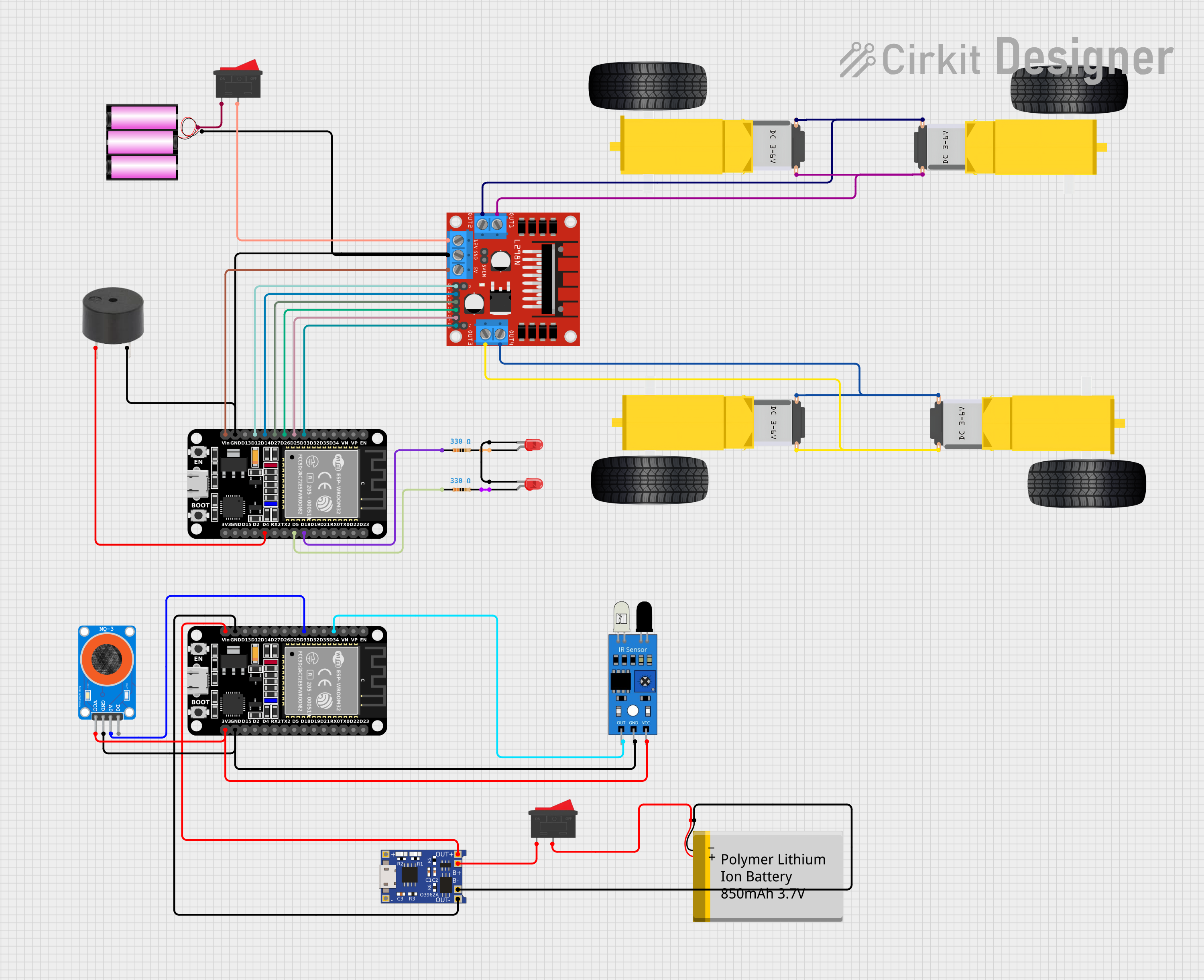
Circuit Documentation
Summary
This document provides a comprehensive overview of a circuit designed to control a set of gearmotors using an ESP32 microcontroller and an L298N DC motor driver. The circuit includes various components such as gearmotors, a 12V battery, switches, an IR sensor, an MQ-3 alcohol sensor, a TP4056 charging module, a polymer lithium-ion battery, buzzers, LEDs, and resistors. The ESP32 microcontroller is programmed to interact with these components, enabling control and feedback mechanisms for a potential robotic or automated system.
Component List
Microcontrollers
- ESP32 (30 pin): A microcontroller with WiFi and Bluetooth capabilities, featuring a wide range of GPIO pins for interfacing with various sensors and actuators.
Motors
- Gearmotor DC Wheels (Right and Left): DC motors with gear reduction that are typically used for driving wheels in robotic applications.
Power Supply
- Battery 12V: A 12-volt battery providing the main power source for the motors and motor driver.
- Polymer Lithium Ion Battery - 850mAh: A rechargeable battery used to power the ESP32 and other low-power components.
- TP4056: A charging module designed for lithium-ion batteries, providing safe charging and power management.
Control
- L298N DC motor driver: An H-bridge motor driver capable of driving two DC motors or one stepper motor.
- Rocker Switch: A switch used to control the power flow from the battery to the motor driver and charging module.
Sensors
- IR Sensor: An infrared sensor used for proximity detection or line tracking.
- MQ-3 Alcohol Sensor: A sensor used to detect alcohol levels in the air.
Indicators
- Buzzer: An audible signaling device.
- LED (Red): Light-emitting diodes used as visual indicators.
Passive Components
- Resistor (330 Ohms): Resistors used to limit current to the LEDs.
Wiring Details
ESP32 (30 pin)
- D33: Connected to L298N DC motor driver ENB.
- D25: Connected to L298N DC motor driver IN4.
- D26: Connected to L298N DC motor driver IN3.
- D27: Connected to L298N DC motor driver IN2.
- D14: Connected to L298N DC motor driver IN1.
- D12: Connected to L298N DC motor driver ENA.
- GND: Common ground with the battery, buzzer, L298N DC motor driver, IR sensor, MQ-3 alcohol sensor, and TP4056.
- Vin: Connected to L298N DC motor driver 5V.
- D18: Connected to a 330 Ohm resistor leading to an LED.
- D5: Connected to a 330 Ohm resistor leading to an LED.
- D4: Connected to the buzzer.
- 3V3: Power supply for the IR sensor and MQ-3 alcohol sensor.
Gearmotors
- DC Wheels Right and Left: Connected to the L298N DC motor driver's output pins.
Battery 12V
- + (Positive): Connected to one terminal of the rocker switch.
- - (Negative): Common ground with the circuit.
Rocker Switch
- Terminal 1: Connected to the 12V battery positive.
- Terminal 2: Connected to the L298N DC motor driver 12V input and the TP4056 B+ pin.
L298N DC motor driver
- OUT1, OUT2, OUT3, OUT4: Connected to the gearmotor DC wheels.
- 12V: Powered through the rocker switch from the 12V battery.
- GND: Common ground with the circuit.
- 5V: Power output to the ESP32 Vin pin.
- ENA, ENB, IN1, IN2, IN3, IN4: Controlled by the ESP32 GPIO pins.
IR Sensor
- Out: Connected to the ESP32 GPIO pin.
- GND: Common ground with the circuit.
- VCC: Powered by the ESP32 3V3 pin.
MQ-3 Alcohol Sensor
- A0: Connected to the ESP32 GPIO pin.
- GND: Common ground with the circuit.
- VCC: Powered by the ESP32 3V3 pin.
TP4056
- OUT-: Connected to the ESP32 GND.
- OUT+: Connected to the ESP32 Vin.
- B-: Connected to the polymer lithium-ion battery GND.
- B+: Connected to the polymer lithium-ion battery VCC through a rocker switch.
Polymer Lithium Ion Battery - 850mAh
- GND: Connected to the TP4056 B-.
- VCC: Connected to the TP4056 B+ through a rocker switch.
Buzzer
- PIN: Connected to the ESP32 GPIO pin.
- GND: Common ground with the circuit.
LED (Red)
- Cathode: Connected to the common cathode of another LED.
- Anode: Connected to a 330 Ohm resistor which is then connected to the ESP32 GPIO pin.
Resistor (330 Ohms)
- Pin 1: Connected to the ESP32 GPIO pin.
- Pin 2: Connected to the anode of the LED.
Documented Code
ESP32 (30 pin) - sketch.ino
void setup() {
  // put your setup code here, to run once:

}

void loop() {
  // put your main code here, to run repeatedly:

}
Note: The provided code is a template and does not include specific functionality. It needs to be populated with the logic to control the motors, read sensors, and activate indicators based on the application requirements.