Cirkit Designer
Your all-in-one circuit design IDE
Home /
Project Documentation
Arduino UNO Controlled Latching Relay Circuit

Circuit Documentation
Summary of the Circuit
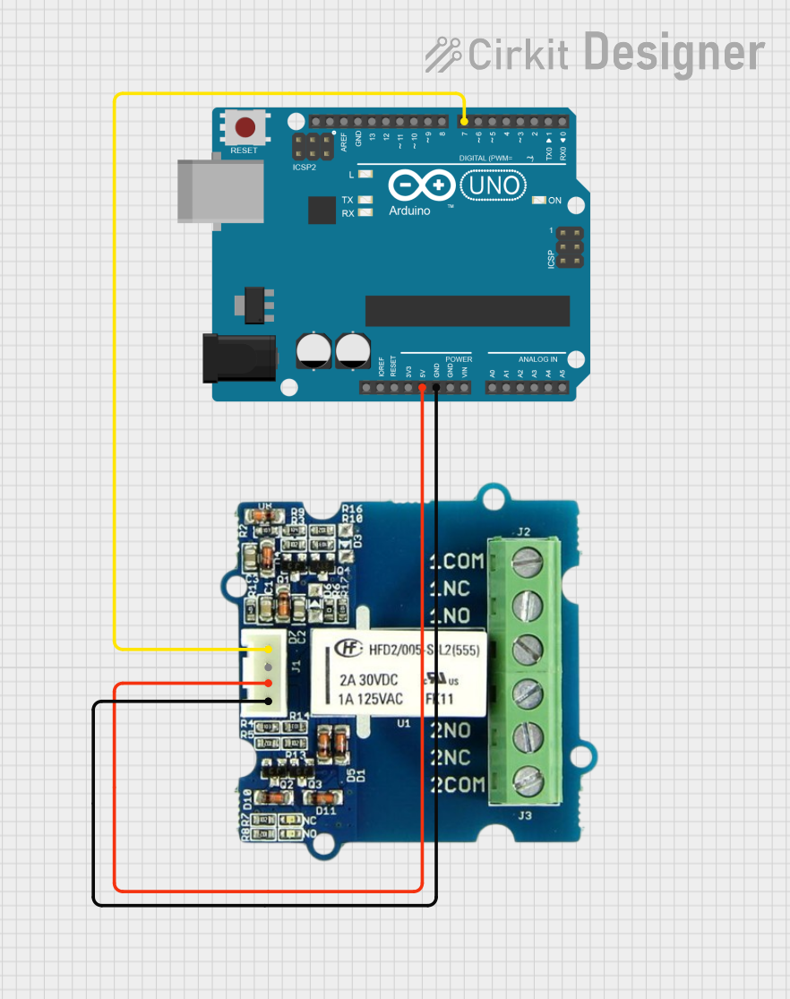
This circuit consists of an Arduino UNO microcontroller board and a 2 Coil Latching Relay. The Arduino UNO is responsible for controlling the relay through one of its digital pins. The relay can be used to switch a separate circuit on or off without exposing the Arduino to the load of that circuit. The relay is powered by the 5V output from the Arduino and is controlled via a digital signal.
Component List
Arduino UNO
- Description: A microcontroller board based on the ATmega328P.
- Pins: UNUSED, IOREF, Reset, 3.3V, 5V, GND, Vin, A0-A5, SCL, SDA, AREF, D0-D13.
- Purpose: Acts as the central controller for the circuit, providing logic and control signals.
2 Coil Latching Relay
- Description: An electrically controlled switch that uses a small current to control a larger current.
- Pins: NC, VCC, GND, SIG.
- Purpose: Allows the Arduino to control high power devices, isolating the microcontroller from the high power circuit.
Wiring Details
Arduino UNO
- 5V: Provides power to the VCC pin of the 2 Coil Latching Relay.
- GND: Connected to the GND pin of the 2 Coil Latching Relay to complete the power circuit.
- D7: Sends control signals to the SIG pin of the 2 Coil Latching Relay.
2 Coil Latching Relay
- VCC: Receives power from the 5V pin of the Arduino UNO.
- GND: Connected to the GND pin of the Arduino UNO to complete the power circuit.
- SIG: Receives control signals from the D7 pin of the Arduino UNO.
Documented Code
Arduino UNO Code (sketch.ino)
void setup() {
  // put your setup code here, to run once:

}

void loop() {
  // put your main code here, to run repeatedly:

}
Additional Notes (documentation.txt)
No additional code documentation provided.
This documentation provides an overview of the circuit components, their wiring, and the initial code structure for the Arduino UNO. Further details, such as the specific functionality of the code and the operation of the relay, would need to be added as the design and implementation progress.