
Raspberry Pi Zero W Obstacle Detection and SOS Alert System with LiDAR and Radar Sensors
View and Edit Project In Cirkit Designer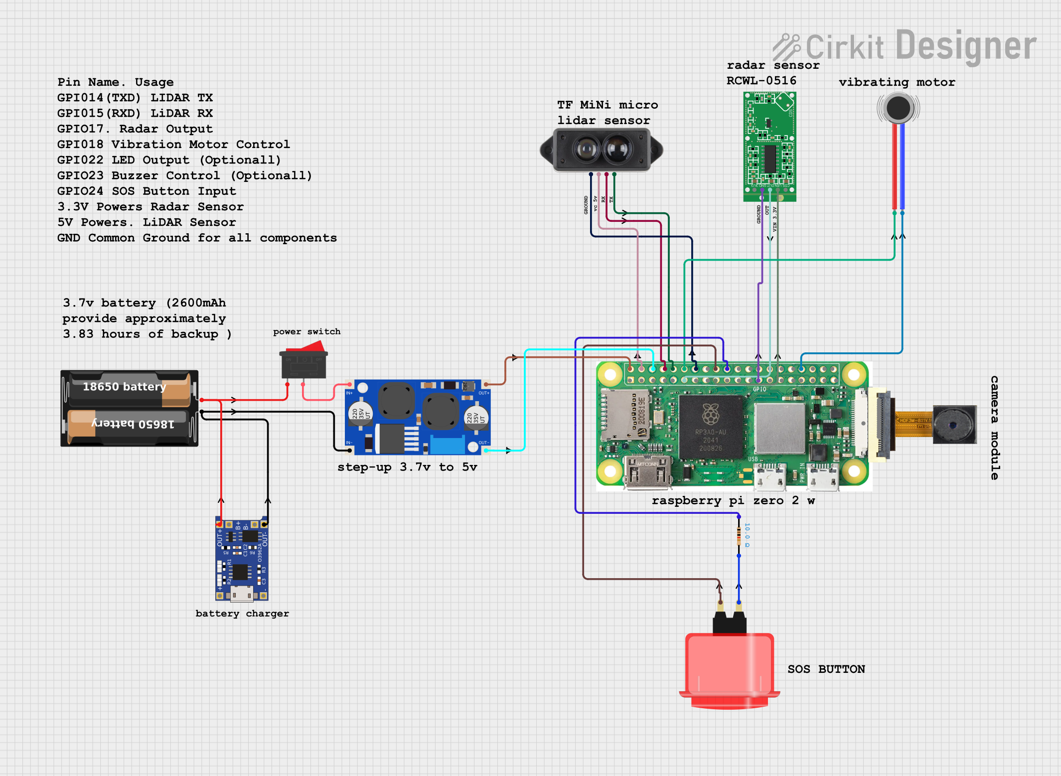
Circuit Documentation
Summary
This circuit integrates various components for real-time obstacle detection, feedback, and SOS alerting. It uses a LiDAR sensor, radar sensor, vibration motor, and an SOS button. The system provides immediate feedback when obstacles are detected and triggers an SOS alert when the button is pressed. The main controller for this circuit is a Raspberry Pi Zero W.
Component List
Raspberry Pi Zero W
- Description: Main microcontroller for the circuit.
- Pins: 5V, 3V3, GPIO2 (SDA), GPIO 3, GROUND, GPIO 14, GPIO15, GPIO 18, GND, GPIO 23, GPIO24, GPIO 25, GPIO 8, GPIO 7, GPIO 1, GPIO 12, GPIO 16, GPIO 20, GPIO 21, GPIO 04, GPIO 17, GPIO 27, GPIO 22, GPIO 10, GPIO 9, GPIO 11, GPIO 0, GPIO 5, GPIO 6, GPIO 13, GPIO 19, GPIO 26, CSI (CAMERA)
OV2640 Camera Module
- Description: Camera module for capturing images.
- Pins: 3.3V, GND, SIOC, SIOD, VSync, HRef, PCLK, XCLK, D9, D8, D7, D6, D5, D4, D3, D2, RET, PWDN
RCWL-0516 Microwave Radar Motion Sensor Module
- Description: Radar sensor for motion detection.
- Pins: CDS, VIN, OUT, GND, 3V3
Vibration Motor
- Description: Motor for providing vibration feedback.
- Pins: POS, NEG
Rocker Switch
- Description: Switch for controlling power.
- Pins: 1, 2
Arcade Button (red)
- Description: Button for triggering SOS alert.
- Pins: no name yet
Resistor
- Description: Resistor with 10 Ohms resistance.
- Pins: pin1, pin2
XL6009E1 Boost Converter
- Description: Boost converter for voltage regulation.
- Pins: IN+, IN-, OUT-, OUT+
Battery Case
- Description: Case for holding the battery.
- Pins: +, -
TP4056
- Description: Battery charging module.
- Pins: OUT-, B-, B+, OUT+, IN-, IN+
LiDAR TF Mini S
- Description: LiDAR sensor for distance measurement.
- Pins: Ground, VC, RX (blue), TX (green)
Wiring Details
Raspberry Pi Zero W
- 5V connected to OUT+ of XL6009E1 Boost Converter
- 5V connected to VC of LiDAR TF Mini S
- GROUND connected to OUT- of XL6009E1 Boost Converter
- GPIO 14 connected to RX (blue) of LiDAR TF Mini S
- GPIO 15 connected to TX (green) of LiDAR TF Mini S
- GPIO 18 connected to POS of Vibration Motor
- GND connected to Ground of LiDAR TF Mini S
- GPIO24 connected to no name yet of Arcade Button (red)
- GND connected to pin1 of Resistor
- GND connected to NEG of Vibration Motor
- GPIO 17 connected to OUT of RCWL-0516 Microwave Radar Motion Sensor Module
- 3V3 connected to VIN of RCWL-0516 Microwave Radar Motion Sensor Module
- GND connected to GND of RCWL-0516 Microwave Radar Motion Sensor Module
XL6009E1 Boost Converter
- OUT+ connected to 5V of Raspberry Pi Zero W
- OUT- connected to GROUND of Raspberry Pi Zero W
- IN+ connected to 2 of Rocker Switch
- IN- connected to OUT- of TP4056 and - of Battery Case
LiDAR TF Mini S
- VC connected to 5V of Raspberry Pi Zero W
- RX (blue) connected to GPIO 14 of Raspberry Pi Zero W
- TX (green) connected to GPIO 15 of Raspberry Pi Zero W
- Ground connected to GND of Raspberry Pi Zero W
Vibration Motor
- POS connected to GPIO 18 of Raspberry Pi Zero W
- NEG connected to GND of Raspberry Pi Zero W
Arcade Button (red)
- no name yet connected to GPIO24 of Raspberry Pi Zero W
- no name yet connected to pin2 of Resistor
Resistor
- pin1 connected to GND of Raspberry Pi Zero W
- pin2 connected to no name yet of Arcade Button (red)
RCWL-0516 Microwave Radar Motion Sensor Module
- OUT connected to GPIO 17 of Raspberry Pi Zero W
- VIN connected to 3V3 of Raspberry Pi Zero W
- GND connected to GND of Raspberry Pi Zero W
Rocker Switch
- 1 connected to OUT+ of TP4056 and + of Battery Case
- 2 connected to IN+ of XL6009E1 Boost Converter
TP4056
- OUT- connected to IN- of XL6009E1 Boost Converter and - of Battery Case
- OUT+ connected to 1 of Rocker Switch and + of Battery Case
Code Documentation
/*
 * This Arduino Sketch integrates various components for real-time obstacle
 * detection, feedback, and SOS alerting. It uses a LiDAR sensor, radar sensor,
 * vibration motor, buzzer, and an SOS button. The system provides immediate
 * feedback when obstacles are detected and triggers an SOS alert when the
 * button is pressed.
 */

// Pin definitions
#define RADAR_PIN 17
#define SOS_BUTTON_PIN 24
#define BUZZER_PIN 18
#define VIBRATION_PIN 18
#define LIDAR_TX_PIN 15
#define LIDAR_RX_PIN 14

// Threshold for obstacle detection
const int OBSTACLE_THRESHOLD = 50; // in cm

void setup() {
  // Initialize GPIO pins
  pinMode(RADAR_PIN, INPUT);
  pinMode(SOS_BUTTON_PIN, INPUT_PULLDOWN);
  pinMode(BUZZER_PIN, OUTPUT);
  pinMode(VIBRATION_PIN, OUTPUT);
  Serial.begin(115200);
  Serial1.begin(115200, SERIAL_8N1, LIDAR_RX_PIN, LIDAR_TX_PIN);
  attachInterrupt(digitalPinToInterrupt(SOS_BUTTON_PIN), sosButtonCallback, RISING);
}

void loop() {
  // Check radar sensor
  if (digitalRead(RADAR_PIN) == HIGH) {
    Serial.println("Radar detected an obstacle!");
    obstacleDetected();
  }
  // Check LiDAR sensor
  if (Serial1.available() >= 9) {
    readLidar();
  }
  delay(100);
}

void readLidar() {
  uint8_t data[9];
  for (int i = 0; i < 9; i++) {
    data[i] = Serial1.read();
  }
  if (data[0] == 0x59 && data[1] == 0x59) { // Valid packet header
    int distance = data[2] + data[3] * 256; // Combine bytes for distance
    if (distance < OBSTACLE_THRESHOLD) {
      obstacleDetected();
    }
  }
}

void obstacleDetected() {
  digitalWrite(VIBRATION_PIN, HIGH); // Vibrate motor
  digitalWrite(BUZZER_PIN, HIGH);    // Activate buzzer
  delay(500);  // Feedback duration
  digitalWrite(VIBRATION_PIN, LOW);
  digitalWrite(BUZZER_PIN, LOW);
}

void sosButtonCallback() {
  Serial.println("SOS Triggered");
  digitalWrite(BUZZER_PIN, HIGH);    // Activate buzzer
  delay(1000);  // SOS alert duration
  digitalWrite(BUZZER_PIN, LOW);
  // Add additional SOS actions here
}
This code initializes the GPIO pins, sets up the LiDAR and radar sensors, and provides functions for obstacle detection and SOS alerting. The setup() function configures the pins and serial communication, while the loop() function continuously checks for obstacles and SOS button presses. The readLidar() function processes