
Arduino UNO and SIM A7670c Based SMS Notification System with Battery Power
View and Edit Project In Cirkit Designer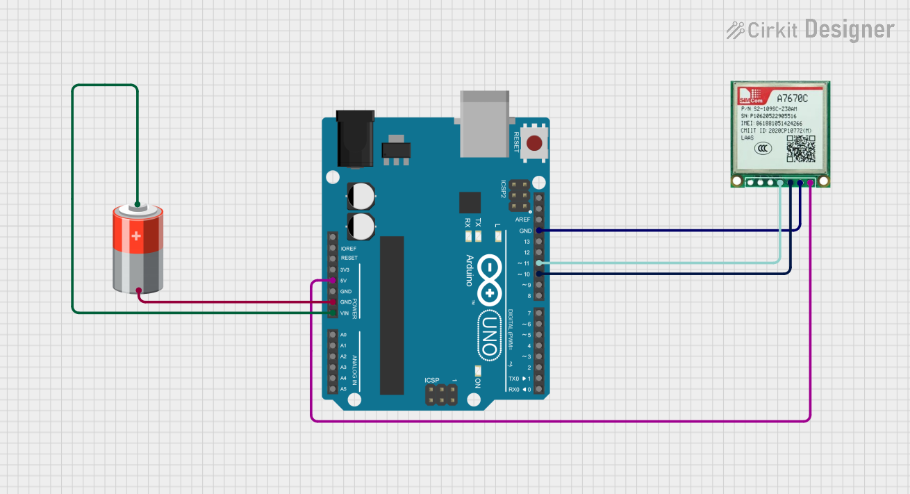
Circuit Documentation
Summary
This circuit involves an Arduino UNO microcontroller, a Sim A7670c GSM module, and a 5V battery. The Arduino UNO is used to control the GSM module and manage power from the battery. The GSM module is used for sending SMS messages based on input from the Arduino. The 5V battery powers the entire circuit.
Component List
Sim A7670c
- Description: GSM module used for sending SMS messages.
- Pins: Vin, Gnd, Tx, Rx
Arduino UNO
- Description: Microcontroller used to control the GSM module and manage power.
- Pins: UNUSED, IOREF, Reset, 3.3V, 5V, GND, Vin, A0, A1, A2, A3, A4, A5, SCL, SDA, AREF, D13, D12, D11, D10, D9, D8, D7, D6, D5, D4, D3, D2, D1, D0
5V Battery
- Description: Power source for the circuit.
- Pins: +, -
Wiring Details
Sim A7670c
- Vin: Connected to Arduino UNO 5V
- Gnd: Connected to Arduino UNO GND
- Tx: Connected to Arduino UNO D10
- Rx: Connected to Arduino UNO D11
Arduino UNO
- 5V: Connected to Sim A7670c Vin
- GND: Connected to Sim A7670c Gnd and 5V Battery -
- Vin: Connected to 5V Battery +
5V Battery
- +: Connected to Arduino UNO Vin
- -: Connected to Arduino UNO GND
Code Documentation
Sim A7670c Code
void setup() {
  // put your setup code here, to run once:

}

void loop() {
  // put your main code here, to run repeatedly:

}
Arduino UNO Code
#include <SoftwareSerial.h>
#include <Wire.h>
#include <LiquidCrystal_I2C.h>

SoftwareSerial GPRS(7, 8); // GSM Module
LiquidCrystal_I2C lcd(0x27, 16, 2); // LCD with I2C

// Pin Definitions
int switchPin = 2;       // Switch for GSM SMS
int pbuttonpin = 4;      // Push button for Relay/LCD
int relaypin = 6;        // Relay Pin

// Variables
boolean state, lastState;
boolean sentRechargeEmpty = false;
boolean sentRechargeDone = false;
boolean lastStateWasLow = false;  // Track if last state was LOW
boolean lastStateWasHigh = false; // Track if last state was HIGH
int val = 0;
int lighton = LOW;
int pushed = 0;
int lastPushed = -1;
int flagl = 0;
int flagh = 0; // To track changes in `pushed`

// Modify sendSMS to accept a string argument
void sendSMS(String message) {
  Serial.println("Sending SMS...");
  GPRS.println("AT+CMGF=1"); // Set SMS mode to text
  delay(500);

  GPRS.println("AT+CMGS=\"+919353009029\""); // Replace with your number
  delay(500);

  GPRS.print(message);  // Send the message as text
  Serial.println(message);
  GPRS.write(0x1A);     // End of SMS
  delay(500);
  Serial.println("SMS Sent.");
}

void setup() {
  // Serial Communication
  Serial.begin(9600);
  Serial.println("Initializing...");

  // Pin Modes
  pinMode(switchPin, INPUT_PULLUP);
  pinMode(pbuttonpin, INPUT_PULLUP);
  pinMode(relaypin, OUTPUT);

  // Initialize LCD
  lcd.init();
  lcd.backlight();
  lcd.setCursor(0, 0);
  lcd.print("System Starting");

  // Initialize GSM Module
  GPRS.begin(9600);
  delay(1000);
  GPRS.println("AT");

  // Initialize State Variables
  state = digitalRead(switchPin);
  lastState = state;
  lighton = digitalRead(pbuttonpin);
  delay(500);
}

void loop() {
  // GSM SMS Logic for Switch
  lastState = state;
  state = digitalRead(switchPin);

  if (state != lastState) {  // Check if state has changed
    delay(50); // Debounce delay to avoid multiple triggers

    // If the state changes to LOW and it's the second time it is LOW
    if (state == LOW) {
      if ((flagl % 2) != 0) {
        sendSMS("Recharge empty.");
        sentRechargeEmpty = true;  // Set flag to prevent sending again
      } else {
        flagl++;
      }
    }
    // If the state changes to HIGH and it's the second time it is HIGH
    if (state == HIGH) {
      if ((flagh % 2) != 0) {
        sendSMS("Recharge done.");
        sentRechargeDone = true;  // Set flag to prevent sending again
      } else {
        flagh++;
      }
    }
  }

  // Relay and LCD Logic for Push Button
  val = digitalRead(pbuttonpin);  // Read the button state
  if (val == HIGH && lighton == LOW) {  // Check if the button is pressed
    delay(50); // Debounce delay
    if (digitalRead(pbuttonpin) == HIGH) {  // Confirm the button press
      pushed = 1 - pushed;  // Toggle the state (0 -> 1 or 1 -> 0)
    }
  }
  lighton = val;  // Update the lighton variable with the current button state

  // Update LCD and Relay Only if State Changes
  if (pushed != lastPushed) {
    lastPushed = pushed;  // Track the previous state to detect changes
    Serial.println("Updating LCD and Relay...");

    if (pushed == HIGH) {
      lcd.setCursor(0, 0);
      lcd.print("LIGHT ON.       ");
      digitalWrite(relaypin, LOW); // Turn ON Relay (assuming LOW turns it ON)
    } else if (pushed == LOW) {
      lcd.setCursor(0, 0);
      lcd.print("LIGHT OFF.      ");
      digitalWrite(relaypin, HIGH); // Turn OFF Relay (assuming HIGH turns it OFF)
    }
  }

  delay(100); // Small delay to stabilize loop
}
5V Battery Code
void setup() {
  // put your setup code here, to run once:

}

void loop() {
  // put your main code here, to run repeatedly:

}