Cirkit Designer
Your all-in-one circuit design IDE
Home /
Project Documentation
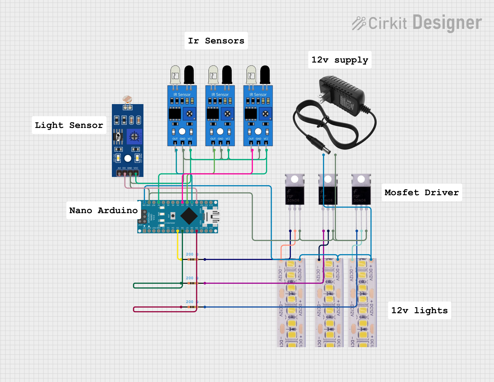
Arduino Nano-Based Smart IR and LDR Controlled LED Lighting System
Circuit Documentation
Summary
This document provides a detailed overview of a circuit that includes various sensors, an Arduino Nano microcontroller, MOSFETs, LED strips, resistors, and a power supply. The circuit is designed to interface with IR sensors and an LDR, control LED strips through MOSFETs, and is powered by a 12V power supply. The Arduino Nano is programmed to manage the inputs and outputs of the circuit.
Component List
IR Sensor
- Pins: out, gnd, vcc
- Description: Infrared sensor used for detecting objects.
- Purpose: To detect objects and send a signal to the microcontroller.
LDR (Light Dependent Resistor)
- Pins: A0, D0, GND, VCC
- Description: Light sensor that changes resistance based on light intensity.
- Purpose: To measure light intensity and send a signal to the microcontroller.
Arduino Nano
- Pins: D1/TX, D0/RX, RESET, GND, D2, D3, D4, D5, D6, D7, D8, D9, D10, D11/MOSI, D12/MISO, VIN, 5V, A7, A6, A5, A4, A3, A2, A1, A0, AREF, 3V3, D13/SCK
- Description: Microcontroller board based on the ATmega328.
- Purpose: To control the circuit by processing inputs from sensors and controlling outputs.
MOSFET
- Pins: Gate, Drain, Source
- Description: Metal-Oxide-Semiconductor Field-Effect Transistor used for switching and amplifying signals.
- Purpose: To control the power to the LED strips.
12V White LED Strip
- Pins: +12V, GND
- Description: LED strip that operates on 12V.
- Purpose: To provide illumination.
Resistor
- Pins: pin1, pin2
- Description: Resistor with a resistance of 200 Ohms.
- Purpose: To limit current in the circuit.
12V Power Supply
- Pins: +, -
- Description: Power supply providing 12V.
- Purpose: To power the circuit.
Wiring Details
IR Sensor
- out connected to A1 of Arduino Nano
- gnd connected to GND of Arduino Nano
- vcc connected to 5V of Arduino Nano
IR Sensor
- out connected to A2 of Arduino Nano
- gnd connected to GND of Arduino Nano
- vcc connected to 5V of Arduino Nano
IR Sensor
- out connected to A3 of Arduino Nano
- gnd connected to GND of Arduino Nano
- vcc connected to 5V of Arduino Nano
LDR
- A0 connected to A0 of Arduino Nano
- D0 connected to A0 of Arduino Nano
- GND connected to GND of Arduino Nano
- VCC connected to 5V of Arduino Nano
Arduino Nano
- A1 connected to out of IR Sensor
- A2 connected to out of IR Sensor
- A3 connected to out of IR Sensor
- A0 connected to D0 of LDR
- D5 connected to pin1 of Resistor
- D6 connected to pin1 of Resistor
- D9 connected to pin1 of Resistor
- VIN connected to +12V of 12V White LED Strip and + of 12V Power Supply
- GND connected to Source of MOSFET and - of 12V Power Supply
MOSFET
- Gate connected to pin2 of Resistor
- Drain connected to GND of 12V White LED Strip
- Source connected to GND of Arduino Nano
12V White LED Strip
- +12V connected to VIN of Arduino Nano and + of 12V Power Supply
- GND connected to Drain of MOSFET
Resistor
- pin1 connected to D5, D6, and D9 of Arduino Nano
- pin2 connected to Gate of MOSFET
12V Power Supply
- + connected to +12V of 12V White LED Strip and VIN of Arduino Nano
- - connected to GND of Arduino Nano
Documented Code
Arduino Nano Code (sketch.ino)
void setup() {
  // put your setup code here, to run once:

}

void loop() {
  // put your main code here, to run repeatedly:

}
Documentation (documentation.txt)
This document provides a comprehensive overview of the circuit, including a summary, component list, wiring details, and documented code. The circuit is designed to interface with various sensors and control LED strips using an Arduino Nano microcontroller.