
Arduino-Controlled RFID Solenoid Door Lock with Indicator LEDs and Buzzer
View and Edit Project In Cirkit Designer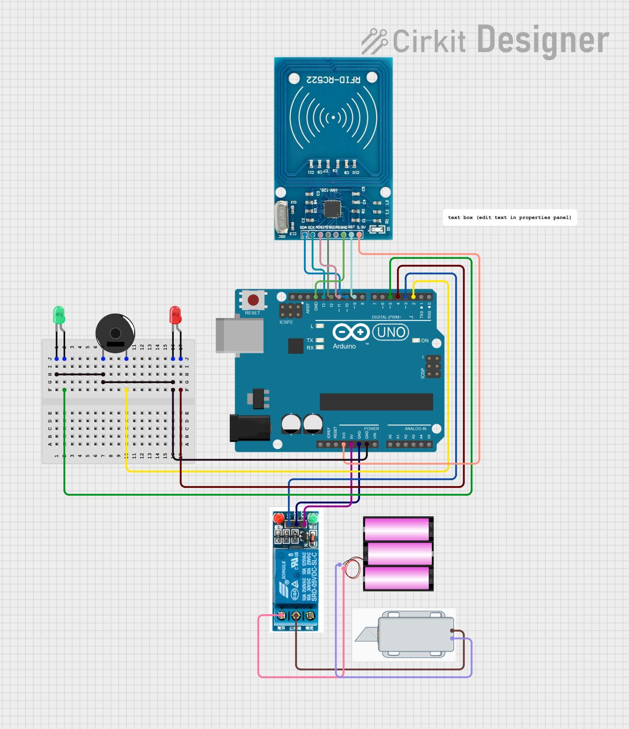
Circuit Documentation
Summary
This circuit is designed to control access using an RFID system that activates a 12V solenoid lock. The system uses an Arduino UNO as the central microcontroller to read RFID tags through an RFID-RC522 module. Depending on the tag's authorization, the system will either activate the solenoid lock (granting access) or deny access with visual and auditory indicators. The visual indicators are a green LED (access granted) and a red LED (access denied), while the auditory indicator is a piezo buzzer.
Component List
- RFID-RC522: An RFID module used for reading RFID tags.
- Piezo Buzzer: An electronic device that emits a tone when activated.
- LED: Two Pin (red): A red LED used as a visual indicator for access denied.
- LED: Two Pin (green): A green LED used as a visual indicator for access granted.
- 5V Relay: An electromechanical switch used to control the high-power solenoid lock with the low-power Arduino.
- Arduino UNO: A microcontroller board based on the ATmega328P, used as the central control unit for the circuit.
- 12V Solenoid Lock: An electrically-controlled lock that is activated by a 12V supply.
- Battery 12V: A 12-volt battery used to power the solenoid lock.
Wiring Details
RFID-RC522
- VCC (3.3V) connected to Arduino UNO 3.3V
- RST connected to Arduino UNO D9
- GND connected to Arduino UNO GND
- IRQ not connected
- MISO connected to Arduino UNO D12
- MOSI connected to Arduino UNO D11
- SCK connected to Arduino UNO D13
- SDA connected to Arduino UNO D10
Piezo Buzzer
- Pin 1 connected to Arduino UNO GND
- Pin 2 connected to Arduino UNO D2
LED: Two Pin (red)
- Cathode connected to Arduino UNO GND
- Anode connected to Arduino UNO D4
LED: Two Pin (green)
- Cathode connected to Arduino UNO GND
- Anode connected to Arduino UNO D5
5V Relay
- VCC connected to Arduino UNO 5V
- GND connected to Arduino UNO GND
- In connected to Arduino UNO D3
- Normally Open connected to Battery 12V +
- Common terminal connected to 12V Solenoid Lock +
12V Solenoid Lock
- + connected to 5V Relay Common terminal
- - connected to Battery 12V -
Battery 12V
- + connected to 5V Relay Normally Open
- - connected to 12V Solenoid Lock -
Documented Code
//Viral Science www.youtube.com/c/viralscience
//RFID Solenoid Lock

#include <SPI.h>
#include <MFRC522.h>

#define SS_PIN 10
#define RST_PIN 9
#define LED_G 5 //define green LED pin
#define LED_R 4 //define red LED
#define RELAY 3 //relay pin
#define BUZZER 2 //buzzer pin
#define ACCESS_DELAY 2000
#define DENIED_DELAY 1000
MFRC522 mfrc522(SS_PIN, RST_PIN);   // Create MFRC522 instance.

void setup()
{
  Serial.begin(9600);   // Initiate a serial communication
  SPI.begin();          // Initiate  SPI bus
  mfrc522.PCD_Init();   // Initiate MFRC522
  pinMode(LED_G, OUTPUT);
  pinMode(LED_R, OUTPUT);
  pinMode(RELAY, OUTPUT);
  pinMode(BUZZER, OUTPUT);
  noTone(BUZZER);
  digitalWrite(RELAY, LOW);
  Serial.println("Put your card to the reader...");
  Serial.println();

}
void loop()
{
  // Look for new cards
  if ( ! mfrc522.PICC_IsNewCardPresent())
  {
    return;
  }
  // Select one of the cards
  if ( ! mfrc522.PICC_ReadCardSerial())
  {
    return;
  }
  //Show UID on serial monitor
  Serial.print("UID tag :");
  String content= "";
  byte letter;
  for (byte i = 0; i < mfrc522.uid.size; i++)
  {
     Serial.print(mfrc522.uid.uidByte[i] < 0x10 ? " 0" : " ");
     Serial.print(mfrc522.uid.uidByte[i], HEX);
     content.concat(String(mfrc522.uid.uidByte[i] < 0x10 ? " 0" : " "));
     content.concat(String(mfrc522.uid.uidByte[i], HEX));
  }
  Serial.println();
  Serial.print("Message : ");
  content.toUpperCase();
  if (content.substring(1) == "83 23 38 BB") //change here the UID of the card/cards that you want to give access
  {
    Serial.println("Authorized access");
    Serial.println();
    delay(500);
    digitalWrite(RELAY, HIGH);
    digitalWrite(LED_G, HIGH);
    delay(ACCESS_DELAY);
    digitalWrite(RELAY, LOW);
    digitalWrite(LED_G, LOW);
  }

 else   {
    Serial.println(" Access denied");
    digitalWrite(LED_R, HIGH);
    tone(BUZZER, 300);
    delay(DENIED_DELAY);
    digitalWrite(LED_R, LOW);
    noTone(BUZZER);
  }
}
This code is designed for an Arduino UNO and includes the necessary libraries and definitions for interfacing with the RFID-RC522 module and controlling the LEDs, buzzer, and relay. The setup() function initializes the serial communication, SPI bus, and sets the pin modes. The loop() function continuously checks for new RFID cards and compares their UID to a predefined authorized UID. If the UID matches, it grants access by activating the relay and green LED. If the UID does not match, it denies access and activates the red LED and buzzer.