Cirkit Designer
Your all-in-one circuit design IDE
Home /
Project Documentation
Arduino UNO-Based Automatic Temperature Control Room Heater with DHT22 Sensor and Relay
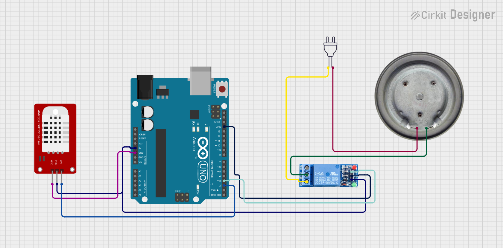
Automatic Temperature Control Room Heater System
Summary
This circuit is designed to automatically control a room heater based on the temperature readings from a DHT22 sensor. The system uses an Arduino UNO to read the temperature and control a relay, which in turn switches the heater element on or off. The goal is to maintain the room temperature above a specified threshold (22.0°C in this case).
Component List
Arduino UNO
- Description: A microcontroller board based on the ATmega328P.
- Pins: UNUSED, IOREF, Reset, 3.3V, 5V, GND, Vin, A0, A1, A2, A3, A4, A5, SCL, SDA, AREF, D13, D12, D11, D10, D9, D8, D7, D6, D5, D4, D3, D2, D1, D0
1 Channel Relay 5V
- Description: A relay module that allows a low-power microcontroller to control a high-power device.
- Pins: VCC, GND, IN, NC, COM, NO
Power 220V
- Description: A standard 220V AC power source.
- Pins: hot wire, neutral wire
DHT22
- Description: A digital temperature and humidity sensor.
- Pins: GND, VCC, DAT
Heater Element
- Description: A resistive heating element.
- Pins: VCC, GND
Wiring Details
Arduino UNO
- 5V: Connected to VCC of DHT22 and VCC of 1 Channel Relay 5V
- GND: Connected to GND of DHT22 and GND of 1 Channel Relay 5V
- D3: Connected to IN of 1 Channel Relay 5V
- D2: Connected to DAT of DHT22
1 Channel Relay 5V
- VCC: Connected to 5V of Arduino UNO
- GND: Connected to GND of Arduino UNO
- IN: Connected to D3 of Arduino UNO
- COM: Connected to VCC of Heater Element
- NO: Connected to hot wire of Power 220V
Power 220V
- hot wire: Connected to NO of 1 Channel Relay 5V
- neutral wire: Connected to GND of Heater Element
DHT22
- VCC: Connected to 5V of Arduino UNO
- GND: Connected to GND of Arduino UNO
- DAT: Connected to D2 of Arduino UNO
Heater Element
- VCC: Connected to COM of 1 Channel Relay 5V
- GND: Connected to neutral wire of Power 220V
Code Documentation
/*
 * Automatic Temperature Control Room Heater System
 *
 * This Arduino sketch reads the temperature from a DHT22 sensor and controls
 * a relay to turn a heater on or off based on the temperature reading. The
 * relay is connected to a heater element, and the system aims to maintain
 * the room temperature above a specified threshold (22.0°C in this case).
 */

#include <DHT.h>

#define DHTPIN 2     // Pin where the DHT22 is connected
#define DHTTYPE DHT22   // DHT 22 (AM2302)
#define RELAY_PIN 3  // Pin where the relay is connected

DHT dht(DHTPIN, DHTTYPE);

void setup() {
  Serial.begin(9600);
  dht.begin();
  pinMode(RELAY_PIN, OUTPUT);
  digitalWrite(RELAY_PIN, LOW); // Ensure the relay is off initially
}

void loop() {
  float temperature = dht.readTemperature();

  if (isnan(temperature)) {
    Serial.println("Failed to read from DHT sensor!");
    return;
  }

  Serial.print("Temperature: ");
  Serial.print(temperature);
  Serial.println(" *C");

  if (temperature < 22.0) { // Set your desired temperature threshold
    digitalWrite(RELAY_PIN, HIGH); // Turn on the heater
  } else {
    digitalWrite(RELAY_PIN, LOW); // Turn off the heater
  }

  delay(2000); // Wait a few seconds between measurements
}
This code initializes the DHT22 sensor and the relay, reads the temperature from the sensor, and controls the relay to turn the heater on or off based on the temperature reading. The system aims to maintain the room temperature above 22.0°C.