Cirkit Designer
Your all-in-one circuit design IDE
Home /
Project Documentation
Arduino UNO-Based Automated Toll Booth with RFID and GSM Notification
Circuit Documentation
Summary
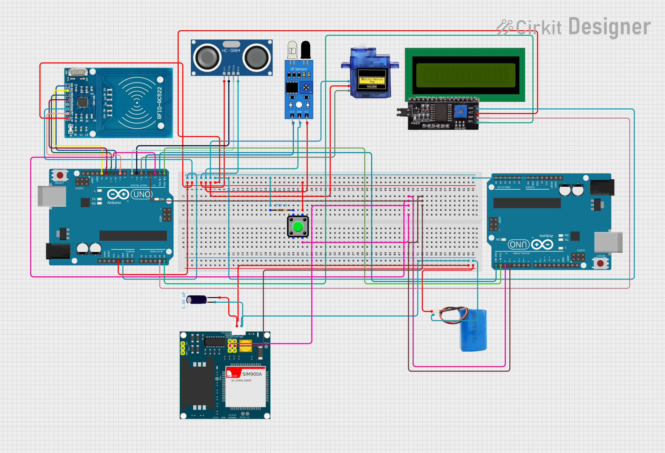
This circuit is designed to function as a toll booth system. It utilizes an Arduino UNO as the main microcontroller to manage various sensors and actuators, including an RFID reader, ultrasonic sensor, IR sensor, servo motor, LCD display, and a GSM module for communication. The system detects vehicles, reads RFID cards for toll payment, and sends SMS notifications upon successful transactions.
Component List
Arduino UNO
- Description: Main microcontroller for the circuit.
- Pins: UNUSED, IOREF, Reset, 3.3V, 5V, GND, Vin, A0, A1, A2, A3, A4, A5, SCL, SDA, AREF, D13, D12, D11, D10, D9, D8, D7, D6, D5, D4, D3, D2, D1, D0
HC-SR04 Ultrasonic Sensor
- Description: Used to detect the presence of a vehicle.
- Pins: VCC, TRIG, ECHO, GND
IR Sensor
- Description: Used to detect the presence of a vehicle at the gate.
- Pins: out, gnd, vcc
Micro Servo 9G
- Description: Controls the gate mechanism.
- Pins: GND, +5V, PWM
16X2 LCD
- Description: Displays messages to the user.
- Pins: VSS, VDD, V0, RS, RW, E, D1, D0, D2, D3, D4, D6, D5, D7, A, K
I2C Module
- Description: Interface for the LCD display.
- Pins: SCL, SDA, VCC, GND
SIM900A
- Description: GSM module for sending SMS notifications.
- Pins: GND, DB9-3 (RXD), DB9-2 (TXD), 5V, 3VR, 5VR, 3VT, 5VT, VCC, Ring, RESTART, RESET, STATUS
Electrolytic Capacitor
- Description: Provides power stabilization.
- Pins: -, +
- Properties: Capacitance: 0.000001 Farads
RFID-RC522
- Description: RFID reader for card detection.
- Pins: VCC (3.3V), RST, GND, IRQ, MISO, MOSI, SCK, SDA
5V Battery
- Description: Power source for the circuit.
- Pins: positive, negative
Pushbutton
- Description: Used to confirm payment.
- Pins: Pin 2, Pin 1, Pin 3, Pin 4
Resistor
- Description: Used for current limiting.
- Pins: pin1, pin2
- Properties: Resistance: 200 Ohms
Wiring Details
Arduino UNO
- 5V: Connected to VCC of RFID-RC522, VCC of HC-SR04 Ultrasonic Sensor, vcc of IR Sensor, +5V of Micro Servo 9G, VCC of I2C Module, Pin 4 of Pushbutton
- GND: Connected to GND of RFID-RC522, GND of HC-SR04 Ultrasonic Sensor, gnd of IR Sensor, GND of Micro Servo 9G, GND of I2C Module, pin1 of Resistor, GND of second Arduino UNO
- D2: Connected to Pin 3 of Pushbutton, D2 of second Arduino UNO, 5VT of SIM900A
- D3: Connected to D3 of second Arduino UNO, 5VR of SIM900A
- A4: Connected to SDA of I2C Module
- A5: Connected to SCL of I2C Module
- D13: Connected to SCK of RFID-RC522
- D12: Connected to MISO of RFID-RC522
- D11: Connected to MOSI of RFID-RC522
- D10: Connected to SDA of RFID-RC522
- D9: Connected to RST of RFID-RC522
- D7: Connected to ECHO of HC-SR04 Ultrasonic Sensor
- D6: Connected to TRIG of HC-SR04 Ultrasonic Sensor
- D5: Connected to PWM of Micro Servo 9G
- D4: Connected to out of IR Sensor
- D1: Connected to D0 of second Arduino UNO
- D0: Connected to D1 of second Arduino UNO
HC-SR04 Ultrasonic Sensor
- VCC: Connected to 5V of Arduino UNO
- GND: Connected to GND of Arduino UNO
- TRIG: Connected to D6 of Arduino UNO
- ECHO: Connected to D7 of Arduino UNO
IR Sensor
- vcc: Connected to 5V of Arduino UNO
- gnd: Connected to GND of Arduino UNO
- out: Connected to D4 of Arduino UNO
Micro Servo 9G
- +5V: Connected to 5V of Arduino UNO
- GND: Connected to GND of Arduino UNO
- PWM: Connected to D5 of Arduino UNO
I2C Module
- VCC: Connected to 5V of Arduino UNO
- GND: Connected to GND of Arduino UNO
- SDA: Connected to A4 of Arduino UNO
- SCL: Connected to A5 of Arduino UNO
SIM900A
- 5V: Connected to + of Electrolytic Capacitor, positive of 5V Battery
- GND: Connected to - of Electrolytic Capacitor, negative of 5V Battery
- 5VT: Connected to D2 of Arduino UNO
- 5VR: Connected to D3 of Arduino UNO
Electrolytic Capacitor
- +: Connected to 5V of SIM900A, positive of 5V Battery
- -: Connected to GND of SIM900A, negative of 5V Battery
RFID-RC522
- VCC (3.3V): Connected to 5V of Arduino UNO
- GND: Connected to GND of Arduino UNO
- SCK: Connected to D13 of Arduino UNO
- MISO: Connected to D12 of Arduino UNO
- MOSI: Connected to D11 of Arduino UNO
- SDA: Connected to D10 of Arduino UNO
- RST: Connected to D9 of Arduino UNO
5V Battery
- positive: Connected to + of Electrolytic Capacitor, 5V of SIM900A
- negative: Connected to - of Electrolytic Capacitor, GND of SIM900A
Pushbutton
- Pin 4: Connected to 5V of Arduino UNO
- Pin 3: Connected to D2 of Arduino UNO
- Pin 1: Connected to pin2 of Resistor
Resistor
- pin1: Connected to GND of Arduino UNO
- pin2: Connected to Pin 1 of Pushbutton
Documented Code
Main Arduino UNO Code
#include <SPI.h>
#include <MFRC522.h>
#include <Servo.h>
#include <LiquidCrystal_I2C.h>
#include <SoftwareSerial.h>

#define RST_PIN 9
#define SS_PIN 10
#define TRIG_PIN 6
#define ECHO_PIN 7
#define IR_PIN 4
#define SERVO_PIN 5
#define BUTTON_PIN 2
#define GSM_TX 3
#define GSM_RX 2

MFRC522 mfrc522(SS_PIN, RST_PIN);
Servo gateServo;
LiquidCrystal_I2C lcd(0x27, 16, 2);
SoftwareSerial gsm(GSM_RX, GSM_TX);

SoftwareSerial serialComm(3, 4);  // RX, TX for communication with second Arduino

// Predefined RFID Cards and Balances
struct RFIDCard {
  String uid;
  int balance;
};

RFIDCard rfidCards[] = {
  {"F3E45216", 200},
  {"A1B2C3D4", 100}
};
const int tollFee = 50;

void setup() {
  Serial.begin(9600);
  SPI.begin();
  mfrc522.PCD_Init();

  lcd.init();
  lcd.backlight();
  lcd.setCursor(0, 0);
  lcd.print("Toll Booth Ready");

  pinMode(TRIG_PIN, OUTPUT);
  pinMode(ECHO_PIN, INPUT);
  pinMode(IR_PIN, INPUT);
  pinMode(BUTTON_PIN, INPUT_PULLUP);

  gateServo.attach(SERVO_PIN);
  gateServo.write(0);

  gsm.begin(115200);
  serialComm.begin(9600);