
Circuit Documentation
Summary of the Circuit
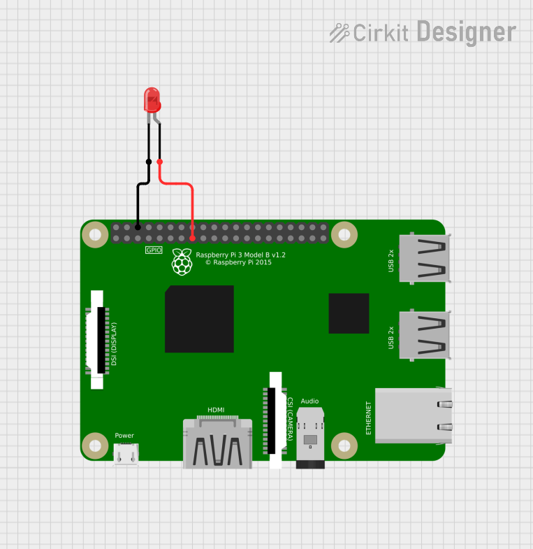
The circuit described in the provided inputs consists of a Raspberry Pi 3B microcontroller board that is used to control a two-pin red LED. The Raspberry Pi 3B is configured to provide a control signal to the anode of the LED via one of its General Purpose Input/Output (GPIO) pins, specifically GPIO22. The cathode of the LED is connected to the ground (GND) pin of the Raspberry Pi 3B, completing the circuit and allowing the LED to be turned on or off by the Raspberry Pi 3B.
Component List
Raspberry Pi 3B
- Description: A microcontroller board capable of performing various computing tasks and interfacing with external hardware via its GPIO pins.
- Pins: 3v3, GPIO2, GPIO3, GPIO4, GND, GPIO17, GPIO27, GPIO22, 3V3, GPIO10, GPIO9, GPIO11, ID_SD, GPIO5, GPIO6, GPIO13, GPIO19, GPIO26, GPIO21, GPIO20, GPIO16, GPIO12, ID_SC, GPIO7, GPIO8, GPIO25, GPIO24, GPIO23, GPIO18, GPIO15, GPIO14, 5V
- Purpose in Circuit: Acts as the control unit for the LED, providing power and control signals.
LED: Two Pin (red)
- Description: A simple light-emitting diode with two pins: an anode and a cathode.
- Pins: cathode, anode
- Purpose in Circuit: Emits light when powered, indicating the status or serving as a visual output.
Wiring Details
Raspberry Pi 3B
- GPIO22 is connected to the anode of the LED.
- GND is connected to the cathode of the LED.
LED: Two Pin (red)
- Anode is connected to GPIO22 on the Raspberry Pi 3B.
- Cathode is connected to GND on the Raspberry Pi 3B.
Documented Code
There is no code provided for the microcontroller in this circuit. Typically, the code would be used to control the state of the GPIO pins on the Raspberry Pi 3B, thereby turning the LED on or off. Since no code is available, it is assumed that the user will develop their own software to control the LED via the Raspberry Pi 3B.