
ESP32-Based Environmental Monitoring and Home Automation System with Ethernet Connectivity
View and Edit Project In Cirkit Designer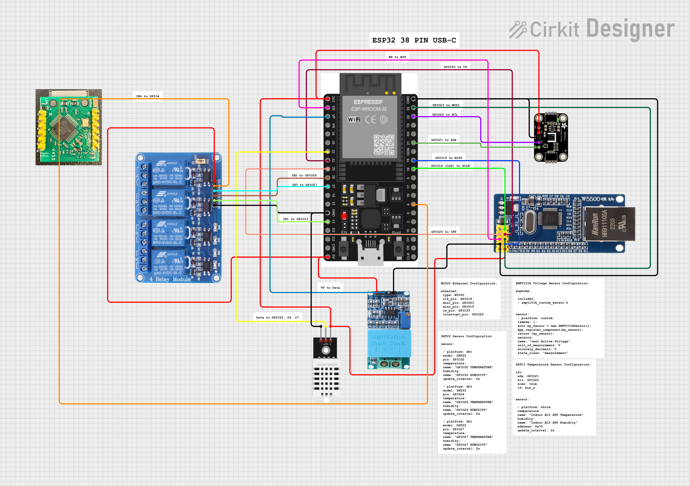
Circuit Documentation
Summary
This circuit integrates various components to perform tasks involving Ethernet communication, temperature and humidity sensing, voltage sensing, and relay control. The core of the circuit is an ESP32 microcontroller, which interfaces with a W5500 Ethernet module for network connectivity, a DHT22 sensor for temperature and humidity readings, an SHTC3 sensor for additional temperature and humidity data, a ZMPT101B module for voltage sensing, and a 4-channel 5V relay module for controlling external devices.
Component List
Module Ethernet W5500
- Description: Ethernet module based on the W5500 chip, used for network communications.
- Pins: NC, INT, RST, GND, 5V, SCK, SS, MOSI, MISO, 3.3V
DHT22
- Description: Digital temperature and humidity sensor.
- Pins: +, Out, -
Adafruit SHTC3 STEMMA QT
- Description: Digital temperature and humidity sensor with I2C interface.
- Pins: VCC, 3.3V, GND, SCL, SDA
ZMPT101B
- Description: Module for AC voltage sensing.
- Pins: OUT, GND, VCC, NEUTRO, FASE
ESP32 38 PINS
- Description: Microcontroller with Wi-Fi and Bluetooth capabilities.
- Pins: GND, 23, 22/SCL, 1, 2, 21/SDA, 19, 18, 5, 17/TX2, 16/RX2, 4, 0, 15, D1, D0, CLK, 3V3, EN, VP, VN, 34, 35, 32, 33, 25, 26, 27, 14, 12, 13, D2, D3, 11, 5V/VIN
Relay 4 Channel 5v
- Description: 4-channel relay module for controlling high power devices.
- Pins: GND, IN1, IN2, IN3, IN4, VCC, COM1, COM2, COM3, COM4, NO1, NO2, NO3, NO4, NC1, NC2, NC3, NC4
Wiring Details
Module Ethernet W5500
- INT connected to ESP32 pin 25
- RST connected to ESP32 pin EN
- GND connected to common ground
- SCK connected to ESP32 pin 18
- SS connected to ESP32 pin 33
- MOSI connected to ESP32 pin 23
- MISO connected to ESP32 pin 19
- 3.3V connected to ESP32 pin 3V3
DHT22
-
- connected to ESP32 pin 3V3
- Out connected to ESP32 pin 32
-
- connected to common ground
Adafruit SHTC3 STEMMA QT
- 3.3V connected to ESP32 pin 3V3
- GND connected to common ground
- SCL connected to ESP32 pin 22/SCL
- SDA connected to ESP32 pin 21/SDA
ZMPT101B
- OUT connected to ESP32 pin VP
- GND connected to common ground
- VCC connected to ESP32 pin 5V/VIN
ESP32 38 PINS
- GND connected to common ground
- 3V3 connected to 3.3V power supply
- 5V/VIN connected to 5V power supply
- Pins 18, 19, 23, 25, 32, 33, 22/SCL, 21/SDA connected as per above components
Relay 4 Channel 5v
- GND connected to common ground
- VCC connected to ESP32 pin 5V/VIN
- IN1 connected to ESP32 pin 13
- IN2 connected to ESP32 pin 26
- IN3 connected to ESP32 pin 27
- IN4 connected to ESP32 pin 4
Documented Code
Microcontroller Code (ESP32)
sketch.ino
void setup() {
  // put your setup code here, to run once:

}

void loop() {
  // put your main code here, to run repeatedly:

}
documentation.txt
(No additional documentation provided)
This concludes the documentation for the given circuit. The circuit is designed to perform multiple sensing and control tasks, with the ESP32 microcontroller acting as the central processing unit. The provided code is a template and will need to be filled in with the logic required to initialize and control the various components in the circuit.