
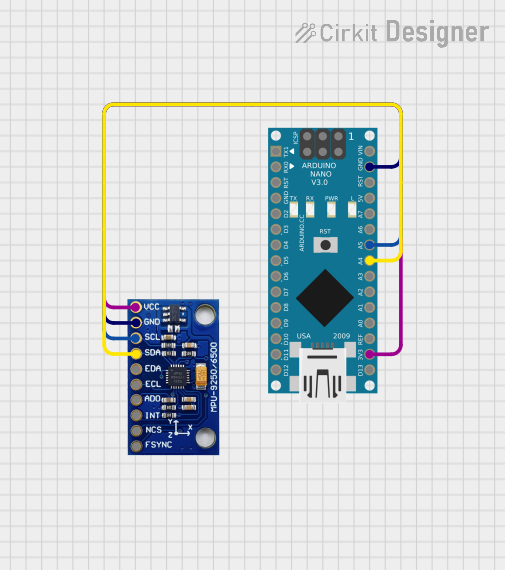
Circuit Documentation
Summary
This circuit involves an Arduino Nano microcontroller interfaced with an MPU-9250/6500/9255 sensor module. The Arduino Nano reads data from the MPU-9250/6500/9255 sensor, which includes accelerometer, gyroscope, and magnetometer data. The data is processed using Madgwick and Mahony filter algorithms to provide orientation information.
Component List
Arduino Nano
- Description: A small, complete, and breadboard-friendly board based on the ATmega328P.
- Pins:
- D1/TX
- D0/RX
- RESET
- GND
- D2
- D3
- D4
- D5
- D6
- D7
- D8
- D9
- D10
- D11/MOSI
- D12/MISO
- VIN
- 5V
- A7
- A6
- A5
- A4
- A3
- A2
- A1
- A0
- AREF
- 3V3
- D13/SCK
MPU-9250/6500/9255
- Description: A 9-axis motion tracking device that combines a 3-axis gyroscope, a 3-axis accelerometer, and a 3-axis magnetometer.
- Pins:
- VCC
- GND
- SCL/SCLK
- SDA/SDI
- EDA
- ECL
- ADO/SDO
- INT
- NCS
- FSYNC
Wiring Details
Arduino Nano
- GND: Connected to GND of MPU-9250/6500/9255
- A5: Connected to SCL/SCLK of MPU-9250/6500/9255
- A4: Connected to SDA/SDI of MPU-9250/6500/9255
- 3V3: Connected to VCC of MPU-9250/6500/9255
MPU-9250/6500/9255
- GND: Connected to GND of Arduino Nano
- SCL/SCLK: Connected to A5 of Arduino Nano
- SDA/SDI: Connected to A4 of Arduino Nano
- VCC: Connected to 3V3 of Arduino Nano
Code Documentation
/*
 * This Arduino sketch demonstrates basic MPU-9250 functionality including
 * parameterizing the register addresses, initializing the sensor, and
 * getting properly scaled accelerometer, gyroscope, and magnetometer data.
 * Additionally, it includes 9 DoF sensor fusion using open source Madgwick
 * and Mahony filter algorithms. The sketch also includes magnetometer
 * register access and user-defined trim values for the accelerometer.
 * The code also sets up motion and zero-motion detection thresholds.
 */

#include <Wire.h>
#include <MPU9250.h>
#include <MadgwickAHRS.h>
#include <MahonyAHRS.h>

// Function prototypes
void readBytes(uint8_t address, uint8_t subAddress, uint8_t count, uint8_t * dest);
uint8_t readByte(uint8_t address, uint8_t subAddress);
void writeByte(uint8_t address, uint8_t subAddress, uint8_t data);
void MPU9250SelfTest(float * destination);
void calibrateMPU9250(float * dest1, float * dest2);
void initMPU9250();
void getMres();
void getGres();
void getAres();
void readAccelData(int16_t * destination);
void readGyroData(int16_t * destination);
void readMagData(int16_t * destination);
int16_t readTempData();
void initAK8963(float * destination);

#define MPU9250_ADDRESS 0x68  // Device address when ADO = 0
#define AK8963_ADDRESS 0x0C   // Address of magnetometer
#define AK8963_WHO_AM_I 0x00  // should return 0x48
#define AK8963_INFO 0x01
#define AK8963_ST1 0x02  // data ready status bit 0
#define AK8963_XOUT_L 0x03  // data
#define AK8963_XOUT_H 0x04
#define AK8963_YOUT_L 0x05
#define AK8963_YOUT_H 0x06
#define AK8963_ZOUT_L 0x07
#define AK8963_ZOUT_H 0x08
#define AK8963_ST2 0x09  // Data overflow bit 3 and data read error status bit 2
#define AK8963_CNTL 0x0A  // Power down (0000), single-measurement (0001), self-test (1000) and Fuse ROM (1111) modes on bits 3:0
#define AK8963_ASTC 0x0C  // Self test control
#define AK8963_I2CDIS 0x0F  // I2C disable
#define AK8963_ASAX 0x10  // Fuse ROM x-axis sensitivity adjustment value
#define AK8963_ASAY 0x11  // Fuse ROM y-axis sensitivity adjustment value
#define AK8963_ASAZ 0x12  // Fuse ROM z-axis sensitivity adjustment value
#define SELF_TEST_X_GYRO 0x00
#define SELF_TEST_Y_GYRO 0x01
#define SELF_TEST_Z_GYRO 0x02
#define SELF_TEST_X_ACCEL 0x0D
#define SELF_TEST_Y_ACCEL 0x0E
#define SELF_TEST_Z_ACCEL 0x0F
#define SELF_TEST_A 0x10
#define XG_OFFSET_H 0x13  // User-defined trim values for gyroscope
#define XG_OFFSET_L 0x14
#define YG_OFFSET_H 0x15
#define YG_OFFSET_L 0x16
#define ZG_OFFSET_H 0x17
#define ZG_OFFSET_L 0x18
#define SMPLRT_DIV 0x19
#define CONFIG 0x1A
#define GYRO_CONFIG 0x1B
#define ACCEL_CONFIG 0x1C
#define ACCEL_CONFIG2 0x1D
#define LP_ACCEL_ODR 0x1E
#define WOM_THR 0x1F
#define MOT_DUR 0x20  // Duration counter threshold for motion interrupt generation, 1 kHz rate, LSB = 1 ms
#define ZMOT_THR 0x21  // Zero-motion detection threshold bits [7:0]
#define ZRMOT_DUR 0x22  // Duration counter threshold for zero motion interrupt generation, 16 Hz rate, LSB = 64 ms

#define FIFO_EN          0x23
#define I2C_MST_CTRL     0x24
#define I2C_SLV0_ADDR    0x25
#define I2C_SLV0_REG     0x26
#define I2C_SLV0_CTRL    0x27
#define I2C_SLV1_ADDR    0x28
#define I2C_SLV1_REG     0x29
#define I2C_SLV1_CTRL    0x2A
#define I2C_SLV2_ADDR    0x2B
#define I2C_SLV2_REG     0x2C
#define I2C_SLV2_CTRL    0x2D
#define I2C_SLV3_ADDR    0x2E
#define I2C_SLV3_REG     0x2F
#define I2C_SLV3_CTRL    0x30
#define I2C_SLV4_ADDR    0x31
#define I2C_SLV4_REG     0x32
#define I2C_SLV4_DO      0x33
#define I2C_SLV4_CTRL    0x34
#define I2C_SLV4_DI      0x35
#define I2C_MST_STATUS   0x36
#define INT_PIN_CFG      0x37
#define INT_ENABLE       0x38
#define DMP_INT_STATUS   0x39  // Check DMP interrupt
#define INT_STATUS       0x3A
#define ACCEL_XOUT_H     0x3B
#define ACCEL_XOUT_L     0x3C
#define ACCEL_YOUT_H     0x3D
#define ACCEL_YOUT_L     0x3E
#define ACCEL_ZOUT_H     0x3F
#define ACCEL_ZOUT_L     0x40
#define TEMP_OUT_H       0x41
#define TEMP_OUT_L       0x42
#define GYRO_XOUT_H      0x43
#define GYRO_XOUT_L      0x44
#define GYRO_YOUT_H      0x45
#define GYRO_YOUT_L      0x46
#define GYRO_ZOUT_H      0x47
#define GYRO_ZOUT_L      0x48
#define EXT_SENS_DATA_00 0x