Raspberry Pi 5 Controlled Surveillance System with Dual Wide-Angle Cameras and Motorized Movement

Circuit Documentation
Summary
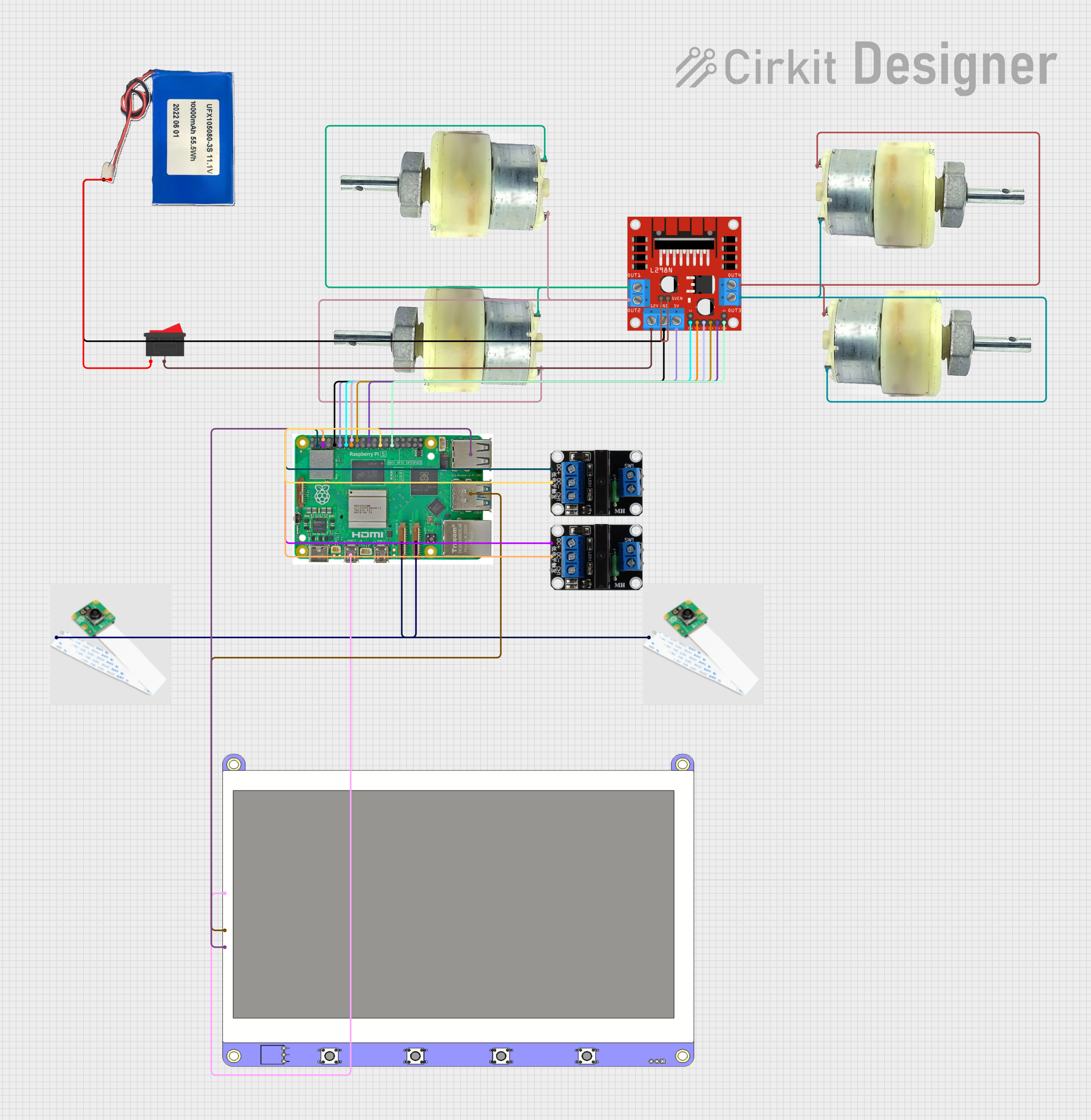
The circuit in question is designed to interface a Raspberry Pi 5 with various peripherals including camera modules, a display, motor drivers, and solid-state relays. It is powered by a Lithium-ion battery and includes a rocker switch for power control. The Raspberry Pi 5 controls the motors through an L298N DC motor driver and captures images from the camera modules. The display is connected via HDMI and USB for power and touch screen functionality. Solid-state relays are used for controlling external devices, possibly for switching power lines. The circuit is designed to be modular, with the ability to control and interact with the connected components programmatically.
Component List
Raspberry Pi 5
- A microcontroller board with multiple GPIO pins and interfaces such as HDMI, USB, Ethernet, and camera ports.
Cam module 3 Wide Angle
- Camera modules that connect to the Raspberry Pi for capturing wide-angle images.
L298N DC motor driver
- A motor driver module that allows the Raspberry Pi to control DC motors.
Rocker Switch
- A mechanical switch used to control the power supply to the circuit.
12V Geared Motor
- DC motors with gear reduction for increased torque.
Display 7 inch
- A 7-inch display with HDMI input and USB connectivity for power and touch screen functionality.
Solid State Relay 1x
- Electronic switching devices that allow the Raspberry Pi to control high power devices.
Lithium-ion Battery 10000mah
- A rechargeable battery providing the power source for the circuit.
Wiring Details
Raspberry Pi 5
Camera 2connected to Cam module 3 Wide AngleMicro HDMI 1connected to Display 7 inch HDMICamera 1connected to another Cam module 3 Wide AngleUSB 3.0connected to Display 7 inch USB PowerUSB 2.0connected to Display 7 inch USB Touch ScreenGNDconnected to Solid State Relay 1x DC-, L298N DC motor driver GND, and Lithium-ion Battery GNDGPIO 23, 24, 25, 2, 3, 17, 27, 22, 5connected to various pins on the L298N DC motor driver for control signalsGPIO 2, 3connected to Solid State Relay 1x DC+ for control signals
Cam module 3 Wide Angle
Camera Pinconnected to Raspberry Pi Camera ports
L298N DC motor driver
IN1, IN2, IN3, IN4, ENA, ENBcontrolled by Raspberry Pi GPIO pinsOUT1, OUT2, OUT3, OUT4connected to 12V Geared Motors12Vconnected to Rocker SwitchGNDconnected to Raspberry Pi GND and Lithium-ion Battery GND5V-ENA-JMP-Ijumpered to5V-ENA-JMP-Ofor enabling motor driver
Rocker Switch
1connected to Lithium-ion Battery 11.1V2connected to L298N DC motor driver 12V
12V Geared Motor
Terminal 1, Terminal 2connected to L298N DC motor driver OUT pins
Display 7 inch
HDMIconnected to Raspberry Pi Micro HDMI 1USB Powerconnected to Raspberry Pi USB 3.0USB Touch Screenconnected to Raspberry Pi USB 2.0
Solid State Relay 1x
CH1not connected (control signal not specified)DC-connected to Raspberry Pi GNDDC+connected to Raspberry Pi GPIO 2 and GPIO 3
Lithium-ion Battery 10000mah
11.1Vconnected to Rocker SwitchGNDconnected to Raspberry Pi GND and L298N DC motor driver GND
Documented Code
Raspberry Pi 5 Code (sketch.ino)
import RPi.GPIO as GPIO
import time
import picamera
import threading
This code snippet imports the necessary libraries for GPIO pin control, time-based functions, camera interface, and threading for concurrent operations on the Raspberry Pi.
Additional Notes
- The code provided is a Python script, not an Arduino sketch (
.ino), despite the file extension. - The actual functionality of the code is not provided, so further implementation details are required to complete the application.
- The
documentation.txtfile is empty, indicating that additional documentation is expected to be written by the user.