Arduino UNO-Based Smart Sensor System with GSM and Motor Control
Circuit Documentation
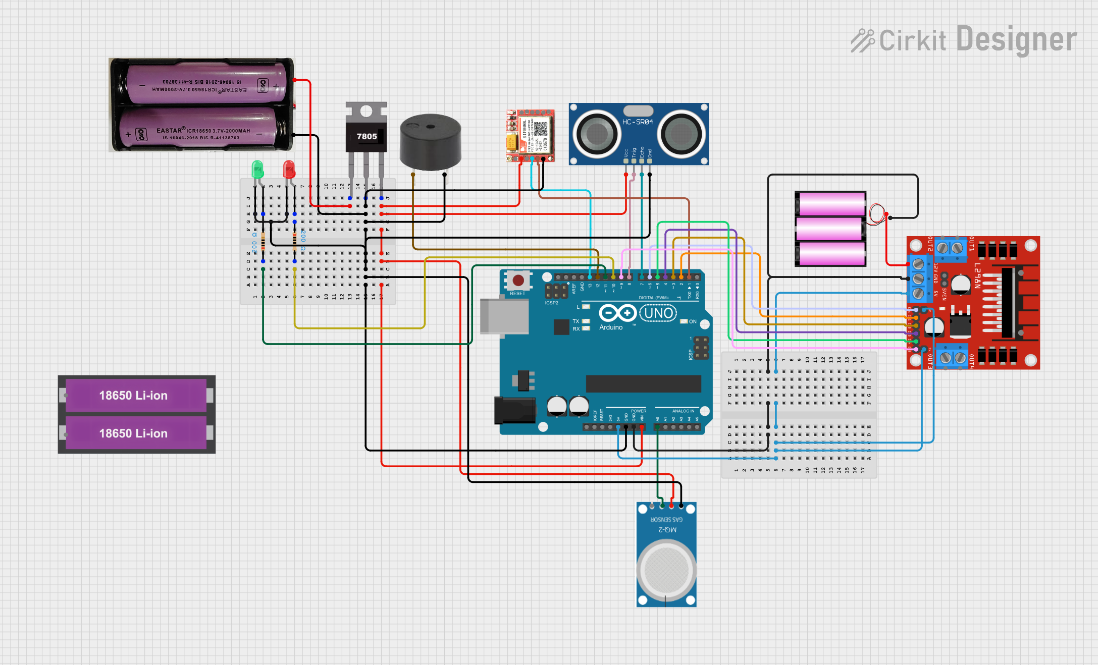
Summary
This circuit involves an Arduino UNO microcontroller interfacing with various sensors, a motor driver, and other components. The circuit is designed to read sensor data, control motors, and communicate via a SIM800L module. Power is managed using a 7805 voltage regulator and multiple power sources.
Component List
Arduino UNO
- Description: Microcontroller board based on the ATmega328P.
- Pins: UNUSED, IOREF, Reset, 3.3V, 5V, GND, Vin, A0, A1, A2, A3, A4, A5, SCL, SDA, AREF, D13, D12, D11, D10, D9, D8, D7, D6, D5, D4, D3, D2, D1, D0
7805
- Description: Voltage regulator providing 5V output.
- Pins: Vin, Gnd, Vout
7.4V Battery
- Description: Power source providing 7.4V.
- Pins: +, -
MQ-2
- Description: Gas sensor for detecting smoke, propane, methane, etc.
- Pins: GND, VCC, ANALOG, Digital
HC-SR04 Ultrasonic Sensor
- Description: Ultrasonic distance sensor.
- Pins: VCC, TRIG, ECHO, GND
L298N DC Motor Driver
- Description: Dual H-Bridge motor driver.
- Pins: OUT1, OUT2, 12V, GND, 5V, OUT3, OUT4, 5V-ENA-JMP-I, 5V-ENA-JMP-O, +5V-J1, +5V-J2, ENA, IN1, IN2, IN3, IN4, ENB
12V Battery
- Description: Power source providing 12V.
- Pins: +, -
SIM800L
- Description: GSM/GPRS module for communication.
- Pins: NFT, RING, VCC, DTR, RST, MIC +, RXD, MIC-, TXD, SPK+, GND, SPK-
Buzzer
- Description: Audio signaling device.
- Pins: PIN, GND
LED: Two Pin (red)
- Description: Red LED.
- Pins: cathode, anode
LED: Two Pin (green)
- Description: Green LED.
- Pins: cathode, anode
Resistor (200 Ohms)
- Description: Resistor with 200 Ohms resistance.
- Pins: pin1, pin2
18650 Li-ion Battery x 2
- Description: Power source providing 7.4V.
- Pins: +, -
Wiring Details
Arduino UNO
GND connected to:
- 12V Battery (-)
- L298N DC Motor Driver (GND)
- 7805 (Gnd)
- MQ-2 (GND)
- HC-SR04 Ultrasonic Sensor (GND)
- 7.4V Battery (-)
- Buzzer (GND)
- SIM800L (GND)
5V connected to:
- L298N DC Motor Driver (+5V-J2, 5V, +5V-J1)
Vin connected to:
- 7805 (Vout)
A0 connected to:
- MQ-2 (ANALOG)
D13 connected to:
- SIM800L (RXD)
D12 connected to:
- Buzzer (PIN)
D11 connected to:
- Resistor (pin1)
D10 connected to:
- Resistor (pin2)
D9 connected to:
- L298N DC Motor Driver (ENB)
D8 connected to:
- HC-SR04 Ultrasonic Sensor (TRIG)
D7 connected to:
- HC-SR04 Ultrasonic Sensor (ECHO)
D6 connected to:
- L298N DC Motor Driver (ENA)
D5 connected to:
- L298N DC Motor Driver (IN4)
D4 connected to:
- L298N DC Motor Driver (IN3)
D3 connected to:
- L298N DC Motor Driver (IN2)
D2 connected to:
- L298N DC Motor Driver (IN1)
D1 connected to:
- SIM800L (TXD)
7805
Vin connected to:
- 7.4V Battery (+)
Gnd connected to:
- Arduino UNO (GND)
Vout connected to:
- Arduino UNO (Vin)
- MQ-2 (VCC)
- HC-SR04 Ultrasonic Sensor (VCC)
- SIM800L (VCC)
7.4V Battery
+ connected to:
- 7805 (Vin)
- connected to:
- Arduino UNO (GND)
MQ-2
GND connected to:
- Arduino UNO (GND)
VCC connected to:
- 7805 (Vout)
ANALOG connected to:
- Arduino UNO (A0)
HC-SR04 Ultrasonic Sensor
VCC connected to:
- 7805 (Vout)
TRIG connected to:
- Arduino UNO (D8)
ECHO connected to:
- Arduino UNO (D7)
GND connected to:
- Arduino UNO (GND)
L298N DC Motor Driver
GND connected to:
- Arduino UNO (GND)
+5V-J2 connected to:
- Arduino UNO (5V)
5V connected to:
- Arduino UNO (5V)
+5V-J1 connected to:
- Arduino UNO (5V)
12V connected to:
- 12V Battery (+)
ENB connected to:
- Arduino UNO (D9)
ENA connected to:
- Arduino UNO (D6)
IN4 connected to:
- Arduino UNO (D5)
IN3 connected to:
- Arduino UNO (D4)
IN2 connected to:
- Arduino UNO (D3)
IN1 connected to:
- Arduino UNO (D2)
12V Battery
+ connected to:
- L298N DC Motor Driver (12V)
- connected to:
- Arduino UNO (GND)
SIM800L
GND connected to:
- Arduino UNO (GND)
VCC connected to:
- 7805 (Vout)
RXD connected to:
- Arduino UNO (D13)
TXD connected to:
- Arduino UNO (D1)
Buzzer
GND connected to:
- Arduino UNO (GND)
PIN connected to:
- Arduino UNO (D12)
LED: Two Pin (red)
cathode connected to:
- LED: Two Pin (green) (cathode)
anode connected to:
- Resistor (pin1)
LED: Two Pin (green)
cathode connected to:
- LED: Two Pin (red) (cathode)
anode connected to:
- Resistor (pin2)
Resistor (200 Ohms)
pin1 connected to:
- Arduino UNO (D11)
- LED: Two Pin (red) (anode)
pin2 connected to:
- Arduino UNO (D10)
- LED: Two Pin (green) (anode)
Documented Code
Arduino UNO Code (sketch.ino)
void setup() {
  // put your setup code here, to run once:

}

void loop() {
  // put your main code here, to run repeatedly:

}
Additional Documentation (documentation.txt)