Cirkit Designer
Your all-in-one circuit design IDE
Home /
Project Documentation
Arduino-Controlled DC Motor with Encoder Feedback and Adjustable Speed

Circuit Documentation
Summary
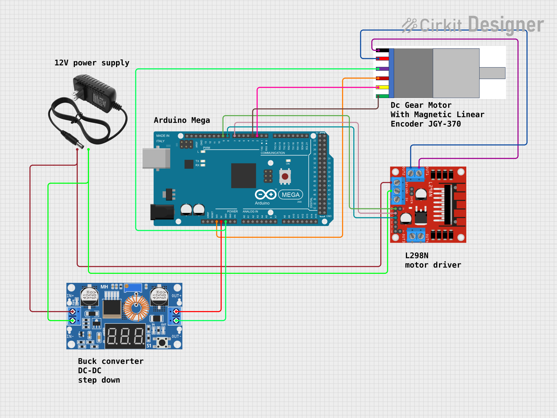
This circuit is designed to control a gear motor with an integrated encoder using an Arduino Mega 2560 microcontroller. The motor is driven by an L298N DC motor driver, which allows for directional control. The motor's encoder provides feedback to the microcontroller for precise speed and position control. A 12V power supply provides the main power, which is stepped down to 5V by an XL4015 DC Buck Step-down module to power the logic level components.
Component List
L298N DC Motor Driver
- Description: A motor driver module capable of driving a DC motor.
- Pins: OUT1, OUT2, 12V, GND, 5V, OUT3, OUT4, 5V-ENA-JMP-I, 5V-ENA-JMP-O, +5V-J1, +5V-J2, ENA, IN1, IN2, IN3, IN4, ENB
Gear Motor with Integrated Encoder
- Description: A DC gear motor with a quadrature encoder for position and speed feedback.
- Pins: MOTOR -, MOTOR+, Encoder -, Encoder +, Encoder A, Encoder B
12V Power Supply
- Description: Provides the main power source for the motor and the motor driver.
- Pins: +, -
XL4015 5A DC Buck Step-down
- Description: A DC-DC step-down (buck) converter module that steps down the voltage from 12V to 5V.
- Pins: Output +, Output -, Input +, Input -
Arduino Mega 2560
- Description: A microcontroller board based on the ATmega2560, with a large number of IO pins, suitable for complex projects.
- Pins: IOREF, RESET, 3V3, 5V, GND, VIN, A0-A15, D0-D53, AREF, SDA, SCL
Wiring Details
L298N DC Motor Driver
- OUT1 connected to Gear Motor (MOTOR -)
- OUT2 connected to Gear Motor (MOTOR+)
- 12V connected to 12V Power Supply (+) and XL4015 (Input +)
- GND connected to 12V Power Supply (-) and XL4015 (Input -)
- ENA connected to Arduino Mega 2560 (D9 PWM)
- IN1 connected to Arduino Mega 2560 (D7 PWM)
- IN2 connected to Arduino Mega 2560 (D8 PWM)
Gear Motor with Integrated Encoder
- MOTOR - connected to L298N DC Motor Driver (OUT1)
- MOTOR+ connected to L298N DC Motor Driver (OUT2)
- Encoder - connected to XL4015 (Output -) and Arduino Mega 2560 (GND)
- Encoder + connected to Arduino Mega 2560 (3V3)
- Encoder A connected to Arduino Mega 2560 (D2 PWM)
- Encoder B connected to Arduino Mega 2560 (D3 PWM)
12V Power Supply
- connected to L298N DC Motor Driver (12V) and XL4015 (Input +)
- connected to L298N DC Motor Driver (GND) and XL4015 (Input -)
XL4015 5A DC Buck Step-down
- Output + connected to Arduino Mega 2560 (5V)
- Output - connected to Gear Motor Encoder (-) and Arduino Mega 2560 (GND)
- Input + connected to L298N DC Motor Driver (12V) and 12V Power Supply (+)
- Input - connected to L298N DC Motor Driver (GND) and 12V Power Supply (-)
Arduino Mega 2560
- D9 PWM connected to L298N DC Motor Driver (ENA)
- D7 PWM connected to L298N DC Motor Driver (IN1)
- D8 PWM connected to L298N DC Motor Driver (IN2)
- GND connected to Gear Motor Encoder (-) and XL4015 (Output -)
- 3V3 connected to Gear Motor Encoder (+)
- D2 PWM connected to Gear Motor Encoder (A)
- D3 PWM connected to Gear Motor Encoder (B)
- 5V connected to XL4015 (Output +)
Documented Code
Arduino Mega 2560 Code (sketch.ino)
void setup() {
  // put your setup code here, to run once:

}

void loop() {
  // put your main code here, to run repeatedly:

}
Note: The provided code is a template and does not contain any functional code to control the motor or read the encoder. It needs to be implemented according to the specific requirements of the application.