
Circuit Documentation
Summary
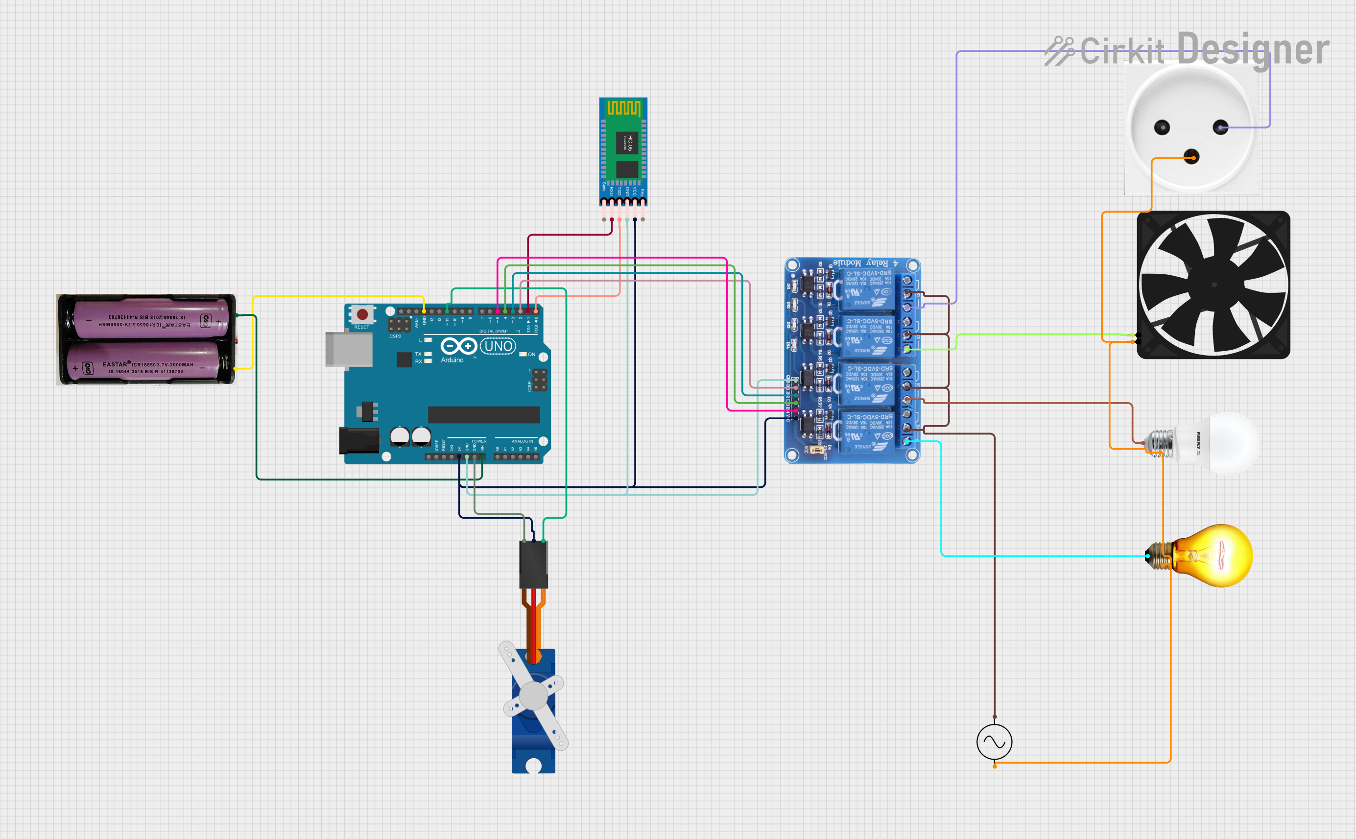
This circuit is designed to control various devices such as a fan, a bulb, and an AC bulb using an Arduino UNO microcontroller. The control is facilitated through a 4-channel relay module and an HC-05 Bluetooth module, allowing wireless communication. Additionally, a Tower Pro SG90 servo motor is included for mechanical actuation. The circuit is powered by a 7.4V battery and an AC supply.
Component List
Arduino UNO
- Description: A microcontroller board based on the ATmega328P.
- Pins: UNUSED, IOREF, Reset, 3.3V, 5V, GND, Vin, A0, A1, A2, A3, A4, A5, SCL, SDA, AREF, D13, D12, D11, D10, D9, D8, D7, D6, D5, D4, D3, D2, D1, D0
Relay 4 Channel 5v
- Description: A relay module that allows control of high voltage devices.
- Pins: GND, IN1, IN2, IN3, IN4, VCC, COM1, COM2, COM3, COM4, NO1, NO2, NO3, NO4, NC1, NC2, NC3, NC4
HC-05 Bluetooth Module
- Description: A Bluetooth module for wireless communication.
- Pins: Key, VCC, TXD, RXD, State, GND
Tower Pro SG90 Servo
- Description: A small servo motor for precise control of angular position.
- Pins: Signal, +5V, GND
BULB
- Description: A standard DC bulb.
- Pins: +, -
Fan
- Description: A 5V DC fan.
- Pins: GND, 5V
Power Outlet (IL)
- Description: A power outlet for AC devices.
- Pins: N, L, GND
7.4V Battery
- Description: A 7.4V battery for powering the circuit.
- Pins: +, -
AC Supply
- Description: An AC power supply.
- Pins: +ve, -ve
AC Bulb
- Description: An AC bulb.
- Pins: P, N
Wiring Details
Arduino UNO
- 5V: Connected to VCC of Relay 4 Channel 5v, VCC of HC-05 Bluetooth Module, and +5V of Tower Pro SG90 Servo.
- GND: Connected to GND of Relay 4 Channel 5v, GND of HC-05 Bluetooth Module, GND of Tower Pro SG90 Servo, and - of 7.4V Battery.
- Vin: Connected to + of 7.4V Battery.
- D11: Connected to Signal of Tower Pro SG90 Servo.
- D5: Connected to IN4 of Relay 4 Channel 5v.
- D4: Connected to IN3 of Relay 4 Channel 5v.
- D3: Connected to IN2 of Relay 4 Channel 5v.
- D2: Connected to IN1 of Relay 4 Channel 5v.
- D1: Connected to RXD of HC-05 Bluetooth Module.
- D0: Connected to TXD of HC-05 Bluetooth Module.
Relay 4 Channel 5v
- VCC: Connected to 5V of Arduino UNO.
- GND: Connected to GND of Arduino UNO.
- IN4: Connected to D5 of Arduino UNO.
- IN3: Connected to D4 of Arduino UNO.
- IN2: Connected to D3 of Arduino UNO.
- IN1: Connected to D2 of Arduino UNO.
- COM1, COM2, COM3, COM4: Connected to +ve of AC Supply.
- NO1: Connected to L of Power Outlet (IL).
- NO2: Connected to 5V of Fan.
- NO3: Connected to + of BULB.
- NO4: Connected to P of AC Bulb.
HC-05 Bluetooth Module
- VCC: Connected to 5V of Arduino UNO.
- GND: Connected to GND of Arduino UNO.
- RXD: Connected to D1 of Arduino UNO.
- TXD: Connected to D0 of Arduino UNO.
Tower Pro SG90 Servo
- Signal: Connected to D11 of Arduino UNO.
- +5V: Connected to 5V of Arduino UNO.
- GND: Connected to GND of Arduino UNO.
BULB
- +: Connected to NO3 of Relay 4 Channel 5v.
- -: Connected to GND of Fan, GND of Power Outlet (IL), N of AC Bulb, and -ve of AC Supply.
Fan
- 5V: Connected to NO2 of Relay 4 Channel 5v.
- GND: Connected to - of BULB.
Power Outlet (IL)
- L: Connected to NO1 of Relay 4 Channel 5v.
- GND: Connected to - of BULB.
7.4V Battery
- +: Connected to Vin of Arduino UNO.
- -: Connected to GND of Arduino UNO.
AC Supply
- +ve: Connected to COM1, COM2, COM3, COM4 of Relay 4 Channel 5v.
- -ve: Connected to - of BULB.
AC Bulb
- P: Connected to NO4 of Relay 4 Channel 5v.
- N: Connected to - of BULB.
Code Documentation
long int ac=2;
long int bulb=3;
long int heater=4;
long int fan=5;
char x;

void setup()
{
    pinMode(ac, OUTPUT);
    pinMode(bulb, OUTPUT);
    pinMode(heater, OUTPUT);
    pinMode(fan, OUTPUT);
    digitalWrite(ac, HIGH);
    digitalWrite(bulb, HIGH);
    digitalWrite(heater, HIGH);
    digitalWrite(fan, HIGH);
    Serial.begin(9600);
}

void loop()
{
    if(Serial.available() > 0)
    {
        x = Serial.read();
    }
    if(x == 'a')
        digitalWrite(ac, LOW);
    if(x == 'b')
        digitalWrite(ac, HIGH);
    if(x == 'c')
        digitalWrite(bulb, LOW);
    if(x == 'd')
        digitalWrite(bulb, HIGH);
    if(x == 'e')
        digitalWrite(heater, LOW);
    if(x == 'f')
        digitalWrite(heater, HIGH);
    if(x == 'g')
        digitalWrite(fan, LOW);
    if(x == 'h')
        digitalWrite(fan, HIGH);
}
This code initializes the pins connected to the relay module as outputs and sets them to a high state (off). It then reads commands from the Bluetooth module to control the state of the relays, thereby controlling the connected devices.