Cirkit Designer
Your all-in-one circuit design IDE
Home /
Project Documentation
Arduino Uno Robotic Arm with Joystick Control and Flex Sensors
Circuit Documentation
Summary
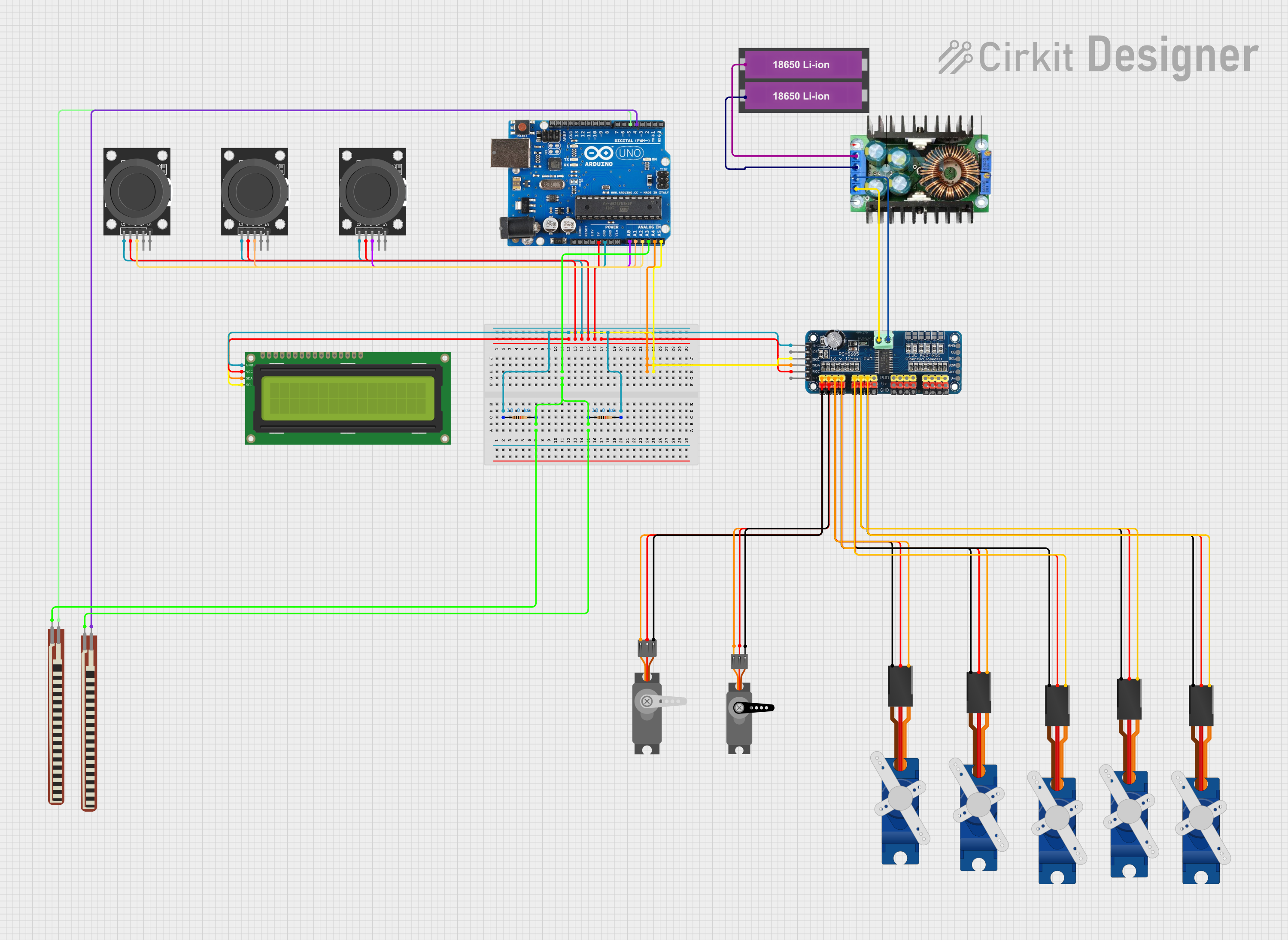
This circuit is designed to control multiple servos using an Arduino Uno R3 microcontroller. It includes a 16-Channel PWM Servo Driver to manage the servos, a 16x2 I2C LCD for display purposes, and several sensors including flex resistors and joystick modules. The circuit is powered by a pair of 18650 Li-ion batteries regulated by an XL4016 module.
Component List
Arduino Uno R3
- Description: Microcontroller board based on the ATmega328P.
- Pins: D8, D9, D10, D11, D12, D13, GND, AREF, SDA, SCL, D0/RX, D1/Tx, D2, D3, D4, D5, 6, D7, A5/SCL, A4/SDA, A3, A2, A1, A0, Vin, 5V, 3.3V, RESET, IOREF, NONE, USB Jack, Power Jack
16-Channel PWM Servo Driver
- Description: PWM driver for controlling up to 16 servos.
- Pins: V+, VCC, SDA, SCL, OE, GND, Vin+, Vin-, PWM1, PWM2, PWM3, PWM4, PWM5, PWM6, PWM7, PWM8, PWM9, PWM10, PWM11, PWM12, PWM13, PWM14, PWM15, PWM16
16x2 I2C LCD
- Description: LCD display with I2C interface.
- Pins: GND, VCC, SDA, SCL
Servo (Wokwi Compatible)
- Description: Standard servo motor.
- Pins: GND, V+, PWM
Servo
- Description: Standard servo motor.
- Pins: GND, VCC, PWM
Tower Pro SG90 Servo
- Description: Micro servo motor.
- Pins: Signal, +5V, GND
2.2 inch Basic Flex Resistor
- Description: Flex sensor for detecting bending.
- Pins: Pin 2, pin 1
KY-023 Dual Axis Joystick Module
- Description: Joystick module with X and Y axis control.
- Pins: GND, +5V, VRx, VRy, SW
XL4016
- Description: DC-DC step-down power supply module.
- Pins: In+, In-GND, Out-GND, Out+
18650 Li-ion Battery x 2
- Description: Rechargeable lithium-ion batteries.
- Pins: +, -
Resistor
- Description: 10k Ohm resistor.
- Pins: pin1, pin2
Wiring Details
Arduino Uno R3
- GND: Connected to GND of 16-Channel PWM Servo Driver, 16x2 I2C LCD, and KY-023 Dual Axis Joystick Modules.
- 5V: Connected to VCC of 16-Channel PWM Servo Driver, 16x2 I2C LCD, and +5V of KY-023 Dual Axis Joystick Modules.
- A3: Connected to pin 1 of 2.2 inch Basic Flex Resistors.
- D4: Connected to Pin 2 of 2.2 inch Basic Flex Resistor.
- D5: Connected to Pin 2 of another 2.2 inch Basic Flex Resistor.
- A0: Connected to VRx of KY-023 Dual Axis Joystick Module.
- A1: Connected to VRx of another KY-023 Dual Axis Joystick Module.
- A2: Connected to VRx of another KY-023 Dual Axis Joystick Module.
- A4/SDA: Connected to SDA of 16-Channel PWM Servo Driver and 16x2 I2C LCD.
- A5/SCL: Connected to SCL of 16-Channel PWM Servo Driver and 16x2 I2C LCD.
16-Channel PWM Servo Driver
- GND: Connected to GND of Arduino Uno R3, Servo (Wokwi Compatible), Servo, and Tower Pro SG90 Servos.
- VCC: Connected to 5V of Arduino Uno R3.
- V+: Connected to V+ of Servo (Wokwi Compatible), VCC of Servo, and +5V of Tower Pro SG90 Servos.
- SDA: Connected to A4/SDA of Arduino Uno R3 and SDA of 16x2 I2C LCD.
- SCL: Connected to A5/SCL of Arduino Uno R3 and SCL of 16x2 I2C LCD.
- PWM1: Connected to PWM of Servo (Wokwi Compatible).
- PWM2: Connected to PWM of Servo.
- PWM3: Connected to Signal of Tower Pro SG90 Servo.
- PWM4: Connected to Signal of another Tower Pro SG90 Servo.
- PWM5: Connected to Signal of another Tower Pro SG90 Servo.
- PWM6: Connected to Signal of another Tower Pro SG90 Servo.
- PWM7: Connected to Signal of another Tower Pro SG90 Servo.
- Vin+: Connected to Out+ of XL4016.
- Vin-: Connected to Out-GND of XL4016.
16x2 I2C LCD
- GND: Connected to GND of Arduino Uno R3.
- VCC: Connected to 5V of Arduino Uno R3.
- SDA: Connected to A4/SDA of Arduino Uno R3 and SDA of 16-Channel PWM Servo Driver.
- SCL: Connected to A5/SCL of Arduino Uno R3 and SCL of 16-Channel PWM Servo Driver.
Servo (Wokwi Compatible)
- GND: Connected to GND of 16-Channel PWM Servo Driver.
- V+: Connected to V+ of 16-Channel PWM Servo Driver.
- PWM: Connected to PWM1 of 16-Channel PWM Servo Driver.
Servo
- GND: Connected to GND of 16-Channel PWM Servo Driver.
- VCC: Connected to V+ of 16-Channel PWM Servo Driver.
- PWM: Connected to PWM2 of 16-Channel PWM Servo Driver.
Tower Pro SG90 Servo
- Signal: Connected to PWM3, PWM4, PWM5, PWM6, PWM7 of 16-Channel PWM Servo Driver.
- +5V: Connected to V+ of 16-Channel PWM Servo Driver.
- GND: Connected to GND of 16-Channel PWM Servo Driver.
2.2 inch Basic Flex Resistor
- Pin 2: Connected to D4, D5 of Arduino Uno R3.
- pin 1: Connected to A3 of Arduino Uno R3.
KY-023 Dual Axis Joystick Module
- GND: Connected to GND of Arduino Uno R3.
- +5V: Connected to 5V of Arduino Uno R3.
- VRx: Connected to A0, A1, A2 of Arduino Uno R3.
XL4016
- In+: Connected to + of 18650 Li-ion Battery x 2.
- In-GND: Connected to - of 18650 Li-ion Battery x 2.
- Out+: Connected to Vin+ of 16-Channel PWM Servo Driver.
- Out-GND: Connected to Vin- of 16-Channel PWM Servo Driver.
18650 Li-ion Battery x 2
- +: Connected to In+ of XL4016.
- -: Connected to In-GND of XL4016.
Resistor
- pin1: Connected to pin2 of another Resistor.
- pin2: Connected to pin1 of another Resistor and GND of Arduino Uno R3.
Code Documentation
#include <Wire.h>
#include <Adafruit_PWMServoDriver.h>
#include <LiquidCrystal_I2C.h>

#define SERVOMIN 102
#define SERVOMAX 492

int joystickMG995Pin = A0;
int joystickMG90Pin = A1;
int joystickSG90Pin = A2;
int flexPin = A3;
int flexPower1 = 4;
int flexPower2 = 5;
int flexThreshold = 110;
int flexThreshold2 = 130;
int servoMG995Channel = 0;
int servoMG90Channel = 1;
int sg90Channels[5] = {2, 3, 4, 5, 6};

Adafruit_PWMServoDriver pwm = Adafruit_PWMServoDriver();

LiquidCrystal_I2C lcd(0x27, 16, 2);

int bendCount1 = 0;
int bendCount2 = 0;
bool isFlexed1 = false;
bool isFlexed2 = false;

int currentMG995Angle = 0;
int stepDelay = 8;

void setup() {
  pwm.begin();
  pwm.setPWMFreq(50);
  Serial.begin(9600);

  pinMode(flexPower1, OUTPUT);
  pinMode(flexPower2, OUTPUT);

  lcd.begin(16, 2);
  lcd.backlight