
Arduino UNO Controlled Robotics Platform with Ultrasonic Sensing and Dot Matrix Display
View and Edit Project In Cirkit Designer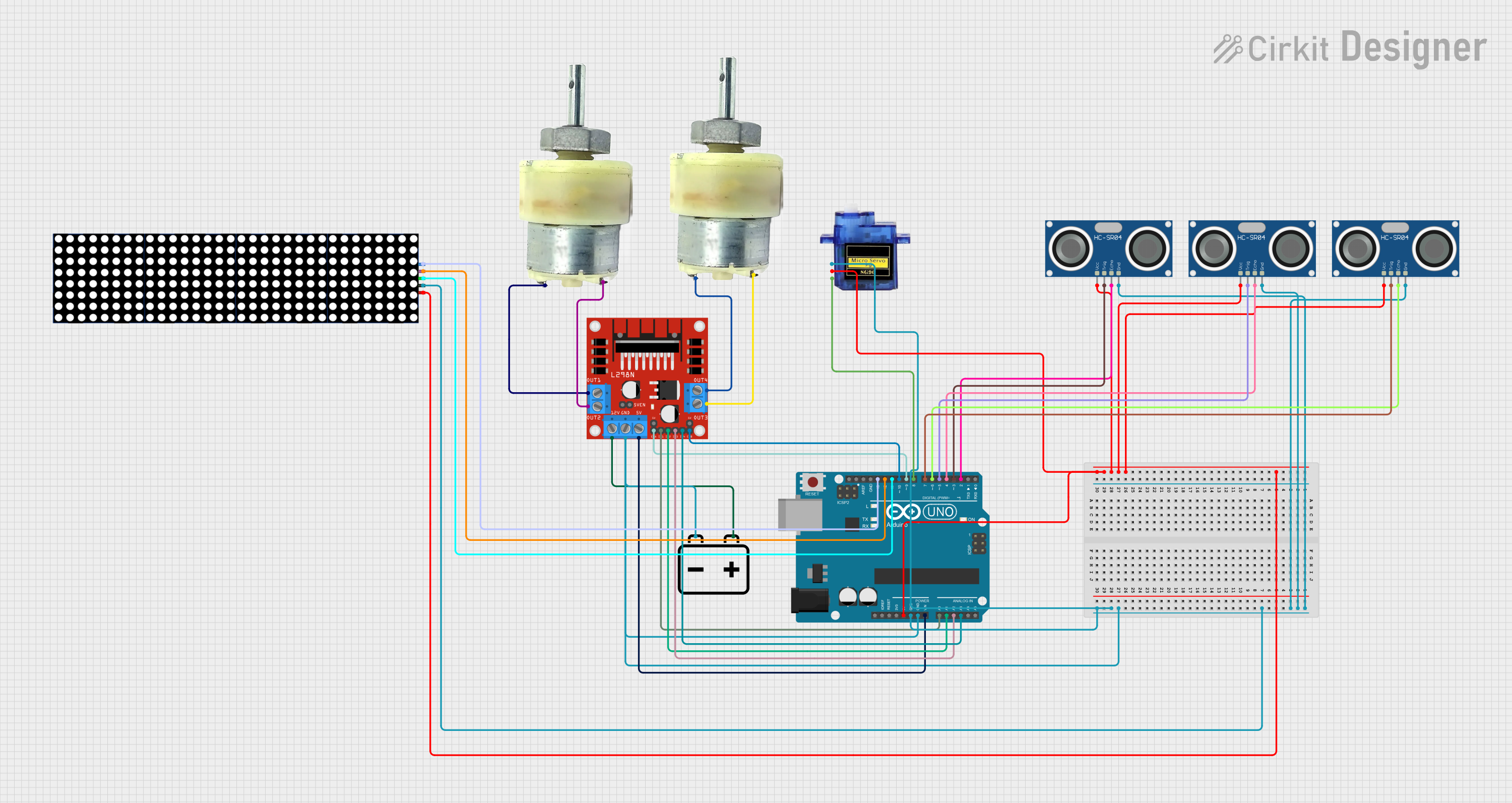
Circuit Documentation
Summary
This circuit is designed to interface various sensors and actuators with an Arduino UNO microcontroller. It includes ultrasonic sensors for distance measurement, a dot matrix display for visual output, servo and geared motors for mechanical movements, and a motor driver to control the motors. The circuit is powered by a 12V battery, with voltage regulation provided by the Arduino UNO and the motor driver for the different voltage requirements of the components.
Component List
Micro servo 9G
- Description: A small and lightweight servo motor used for precise angular movement.
- Pins: GND, +5V, PWM
Arduino UNO
- Description: A microcontroller board based on the ATmega328P, widely used for prototyping and educational purposes.
- Pins: UNUSED, IOREF, Reset, 3.3V, 5V, GND, Vin, A0-A5, SCL, SDA, AREF, D0-D13
12V Battery
- Description: A power source for the circuit, providing 12 volts.
- Pins: -, +
12V Geared Motor
- Description: A motor with a gearbox to provide high torque at lower speeds.
- Pins: Terminal 1, Terminal 2
L298N DC Motor Driver
- Description: A module capable of driving two DC motors or one stepper motor, providing bidirectional drive currents.
- Pins: OUT1, OUT2, 12V, GND, 5V, OUT3, OUT4, 5V-ENA-JMP-I, 5V-ENA-JMP-O, +5V-J1, +5V-J2, ENA, IN1, IN2, IN3, IN4, ENB
HC-SR04 Ultrasonic Sensor
- Description: A sensor for measuring distance via ultrasonic sound waves.
- Pins: VCC, TRIG, ECHO, GND
Dot Matrix 8x32
- Description: An 8x32 LED matrix display for showing patterns or text.
- Pins: +VCC, GND, CS (SS), Data (MOSI), CLK (SCK)
Wiring Details
Micro servo 9G
- GND: Connected to the common ground.
- +5V: Connected to the 5V output from the Arduino UNO.
- PWM: Connected to digital pin D8 on the Arduino UNO.
Arduino UNO
- GND: Connected to the common ground.
- 5V: Provides power to the Micro servo 9G and HC-SR04 Ultrasonic Sensors.
- Vin: Connected to the 5V output from the L298N DC motor driver.
- A0-A3: Connected to IN1-IN4 on the L298N DC motor driver for motor control.
- D2-D13: Various connections to the HC-SR04 Ultrasonic Sensors and Dot Matrix 8x32 for control and data signals.
12V Battery
- -: Connected to the common ground.
- +: Provides power to the L298N DC motor driver.
12V Geared Motors
- Terminal 1 and Terminal 2: Connected to OUT1-OUT4 on the L298N DC motor driver for bidirectional control.
L298N DC Motor Driver
- GND: Connected to the common ground.
- 12V: Powered by the 12V battery.
- 5V: Provides power to the Arduino UNO Vin pin.
- OUT1-OUT4: Connected to the terminals of the 12V Geared Motors for control.
- IN1-IN4: Controlled by the Arduino UNO A0-A3 pins for motor direction.
- ENA, ENB: Connected to digital pins D9 and D10 on the Arduino UNO for motor speed control.
HC-SR04 Ultrasonic Sensors
- GND: Connected to the common ground.
- VCC: Powered by the 5V output from the Arduino UNO.
- TRIG: Connected to digital pins D3, D5, and D7 on the Arduino UNO for triggering measurements.
- ECHO: Connected to digital pins D2, D4, and D6 on the Arduino UNO for receiving the echo signal.
Dot Matrix 8x32
- GND: Connected to the common ground.
- +VCC: Powered by the 5V output from the Arduino UNO.
- CS (SS): Connected to digital pin D11 on the Arduino UNO.
- Data (MOSI): Connected to digital pin D12 on the Arduino UNO.
- CLK (SCK): Connected to digital pin D13 on the Arduino UNO.
Documented Code
Arduino UNO Code (sketch.ino)
void setup() {
  // put your setup code here, to run once:

}

void loop() {
  // put your main code here, to run repeatedly:

}
Note: The provided code is a template and does not contain any functional code. It needs to be populated with the logic to control the components as per the circuit design.