
ESP8266 NodeMCU Controlled Environment Monitoring System with MQTT
View and Edit Project In Cirkit Designer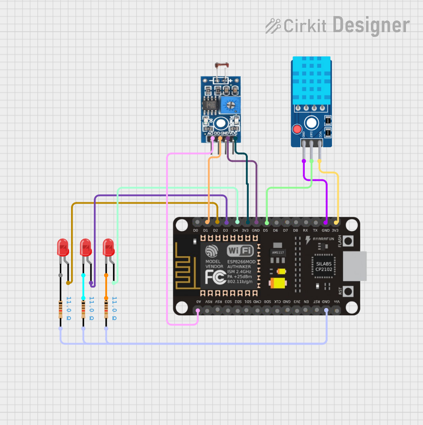
Circuit Documentation
Summary
The circuit in question is designed to interface an ESP8266 NodeMCU microcontroller with a photosensitive sensor module for light intensity detection, a DHT11 temperature and humidity sensor, and three red LEDs. The ESP8266 NodeMCU is programmed to read sensor data and control the LEDs based on MQTT messages received over WiFi. The circuit is powered by the 3.3V supply from the microcontroller, and the LEDs are connected through individual resistors to limit the current.
Component List
Photosensitive Sensor Module Digital Light Intensity Detection
- Pins: Analog Output, Digital Output, Ground, VCC
- Description: This module is used to detect the intensity of light in the environment. It provides both analog and digital outputs.
DHT11 Sensor V2
- Pins: GND, DAT, VCC
- Description: The DHT11 is a basic, ultra low-cost digital temperature and humidity sensor that uses a capacitive humidity sensor and a thermistor to measure the surrounding air.
LED: Two Pin (red)
- Pins: cathode, anode
- Description: A basic red LED used for indication purposes.
Resistor
- Pins: pin1, pin2
- Properties: Resistance: 11 Ohms
- Description: These resistors are used to limit the current through the LEDs to protect them from burning out.
ESP8266 NodeMCU
- Pins: D0, D1, D2, D3, D4, 3V3, GND, D5, D6, D7, D8, RX, TX, A0, RSV, SD3, SD2, SD1, CMD, SD0, CLK, EN, RST, VIN
- Description: The ESP8266 NodeMCU is a low-cost Wi-Fi microchip with full TCP/IP stack and microcontroller capability.
Wiring Details
Photosensitive Sensor Module Digital Light Intensity Detection
- Digital Output connected to ESP8266 NodeMCU D1
- Analog Output connected to ESP8266 NodeMCU A0
- Ground connected to ESP8266 NodeMCU GND
- VCC connected to ESP8266 NodeMCU 3V3
DHT11 Sensor V2
- DAT connected to ESP8266 NodeMCU D5
- GND connected to ESP8266 NodeMCU GND
- VCC connected to ESP8266 NodeMCU 3V3
LED: Two Pin (red)
- Anode of first LED connected to ESP8266 NodeMCU D2
- Anode of second LED connected to ESP8266 NodeMCU D3
- Anode of third LED connected to ESP8266 NodeMCU D4
- Cathode of each LED connected to respective pin1 of a Resistor
Resistor
- Pin2 of each resistor connected to ESP8266 NodeMCU GND
Documented Code
#ifdef ESP8266
#include <ESP8266WiFi.h>
#else
#include <WiFi.h>
#endif

#include <ArduinoJson.h>
#include <PubSubClient.h>
#include <DHT.h>

#define DHTPIN D5
#define DHTTYPE DHT11

#define LDR_PIN A0

const int led1 = 4;
const int led2 = 0;
const int led3 = 2;

const char* ssid = "Nha 17 - P602";
const char* password = "66668888";

// MQTT Broker Connection Details
const char* mqtt_server = "192.168.162.102";
const char* mqtt_username = "LeVanThien1";
const char* mqtt_password = "123";
const int mqtt_port = 1993;

// Create instances
WiFiClient espClient;
PubSubClient client(espClient);
DHT dht(DHTPIN, DHTTYPE);

// Connect to WiFi
void setup_wifi() {
  Serial.print("\nConnecting to ");
  Serial.println(ssid);
  WiFi.mode(WIFI_STA);
  WiFi.begin(ssid, password);

  while (WiFi.status() != WL_CONNECTED) {
    delay(500);
    Serial.print(".");
  }
  Serial.println("\nWiFi connected\nIP address: ");
  Serial.println(WiFi.localIP());
}

// Connect to MQTT Broker
void reconnect() {
  while (!client.connected()) {
    Serial.print("Attempting MQTT connection...");
    String clientId = "ESP8266Client-";
    clientId += String(random(0xFFFF), HEX);

    if (client.connect(clientId.c_str(), mqtt_username, mqtt_password)) {
      Serial.println("MQTT connected");
      client.subscribe("devices/air-conditioner/toggle");
      client.subscribe("devices/fan/toggle");
      client.subscribe("devices/light/toggle");
      client.subscribe("devices/status");
      client.subscribe("devices/toggle");
    } else {
      Serial.print("Failed to connect, rc=");
      Serial.print(client.state());  // In chi tiết lỗi để kiểm tra
      Serial.println(". Trying again in 5 seconds...");
      delay(5000);
    }
  }
}

// Callback for receiving MQTT messages
void callback(char* topic, byte* payload, unsigned int length) {
  String message;
  for (int i = 0; i < length; i++) {
    message += (char)payload[i];
  }

  DynamicJsonDocument doc(200);
  String mqtt_message;

  //Get the status of devices
  if (strcmp(topic, "devices/status") == 0) {
    doc["air-conditioner"] = digitalRead(led1) == HIGH ? "ON" : "OFF";
    doc["fan"] = digitalRead(led2) == HIGH ? "ON" : "OFF";
    doc["light"] = digitalRead(led3) == HIGH ? "ON" : "OFF";
    Serial.printf("Status of all devices");

    serializeJson(doc, mqtt_message);
    publishMessage("devices/status/response", mqtt_message, true);

    String mqtt_message;
    serializeJson(doc, mqtt_message);

    return;
  }

  // Handle toggle device
  if (strcmp(topic, "devices/air-conditioner/toggle") == 0) {
    digitalWrite(led1, message == "ON" ? HIGH : LOW);
    publishMessage("devices/air-conditioner/confirmation", mqtt_message, true);
  } else if (strcmp(topic, "devices/fan/toggle") == 0) {
    digitalWrite(led2, message == "ON" ? HIGH : LOW);
    publishMessage("devices/fan/confirmation", mqtt_message, true);
  } else if (strcmp(topic, "devices/light/toggle") == 0) {
    digitalWrite(led3, message == "ON" ? HIGH : LOW);
    publishMessage("devices/light/confirmation", mqtt_message, true);
  } else if(strcmp(topic, "devices/toggle") == 0) {
    digitalWrite(led1, message == "ON" ? HIGH : LOW);
    digitalWrite(led2, message == "ON" ? HIGH : LOW);
    digitalWrite(led3, message == "ON" ? HIGH : LOW);
  }


  doc["status"] = message;
  serializeJson(doc, mqtt_message);
}

// Publish MQTT messages
void publishMessage(const char* topic, const String& payload, boolean retained) {
  if (client.publish(topic, payload.c_str(), retained)) {
    Serial.println("Message published [" + String(topic) + "]: " + payload);
  }
}

void setup() {
  Serial.begin(115200);
  dht.begin();
  delay(2000);

  setup_wifi();
  client.setServer(mqtt_server, mqtt_port);
  client.setCallback(callback);

  Serial.print("Pinging ");
  Serial.print(mqtt_server);
  Serial.println("...");

  pinMode(led1, OUTPUT);
  pinMode(led2, OUTPUT);
  pinMode(led3, OUTPUT);
}

void loop() {
  if (!client.connected()) {
    reconnect();
  }
  client.loop();

  // Read DHT11 values
  float humidity = dht.readHumidity();
  float temperature = dht.readTemperature();
  int light = analogRead(LDR_PIN);
  // Check for errors
  if (isnan(humidity) || isnan(temperature)) {
    Serial.println("Error reading from DHT11!");
    return;
  }

  DynamicJsonDocument doc(128);
  doc["humidity"] = humidity;
  doc["temperature"] = temperature;
  doc["light"] = light;

  String mqtt_message;
  serializeJson(doc, mqtt_message);
  publishMessage("datasensor", mqtt_message, true);

  delay(2000);
}
This code is designed to run on an ESP8266 NodeMCU microcontroller. It includes functionality to connect to a WiFi network, interface with an MQTT broker, read sensor data from a DHT11 sensor and a light-dependent resistor (LDR), and control LEDs based on MQTT commands. The code uses the ArduinoJson library for JSON handling and the PubSubClient library for MQTT communication.