ESP32-Based Smart Alarm Clock with I2C LCD Display and Bluetooth Connectivity
Circuit Documentation
Summary
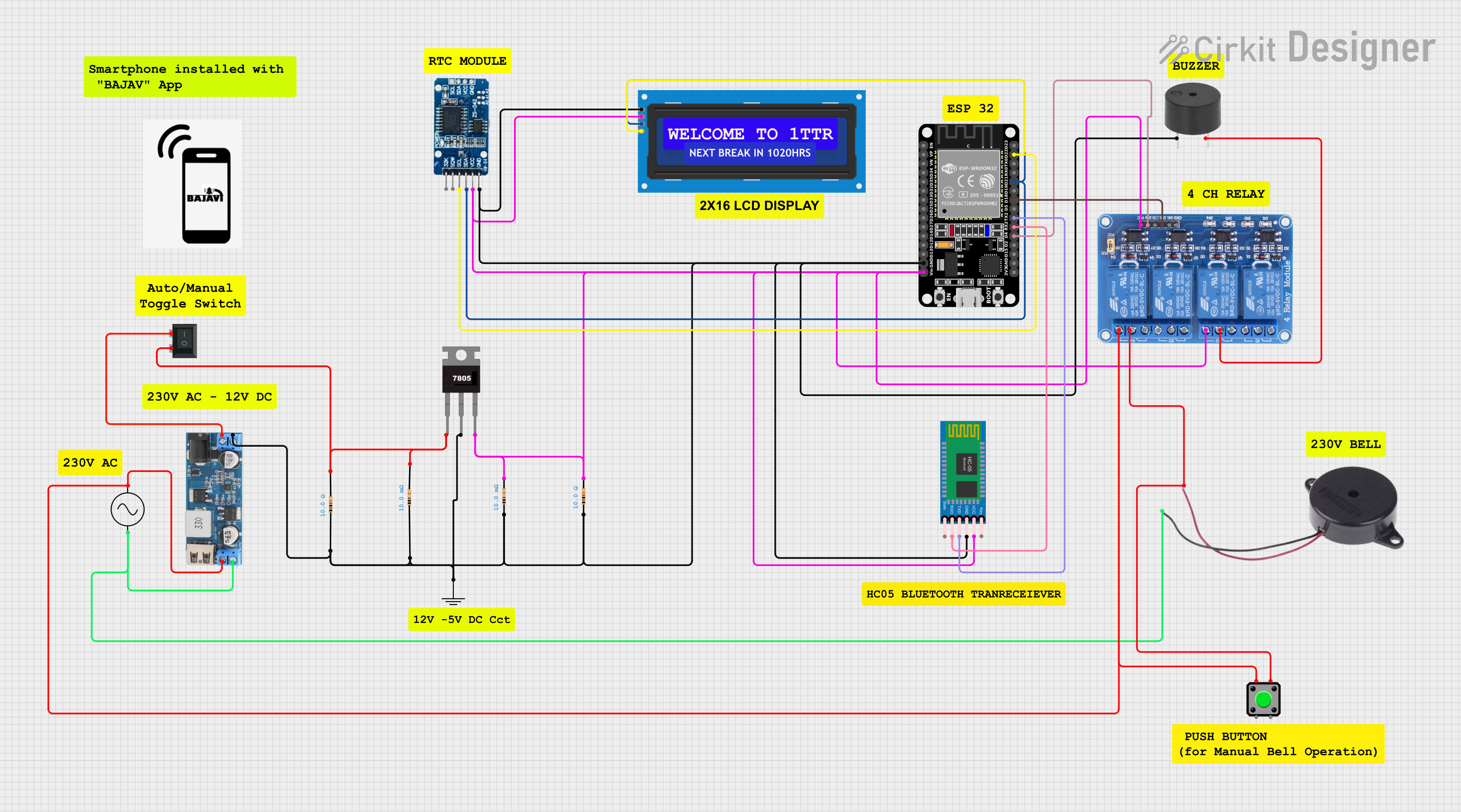
This circuit is designed around the ESP32 microcontroller, which is a versatile and powerful chip with a wide range of I/O capabilities. The circuit includes a 7805 voltage regulator to provide a stable 5V supply, a real-time clock (RTC) module (DS3231) for timekeeping, a 4-channel 5V relay module for controlling external devices, and a buzzer for audible alerts. Additionally, the circuit features an LCD screen with I2C interface for display purposes, a step-down power converter to convert 12V to 5V, and various resistors for current limiting and pull-up/pull-down purposes. An AC supply is used to provide power to the circuit, and a pushbutton and rocker switch are included for user input. The HC-05 Bluetooth module allows for wireless communication. The circuit is designed to be interfaced with a phone, although the phone's specific role is not detailed in the provided information.
Component List
- ESP32 (30 pin): A microcontroller with Wi-Fi and Bluetooth capabilities, featuring a variety of digital and analog pins.
- 7805: A voltage regulator that outputs a stable 5V from a higher voltage input.
- Resistor: A passive two-terminal electrical component that implements electrical resistance as a circuit element.
- RTC DS3231: A highly accurate I2C real-time clock with an integrated temperature-compensated crystal oscillator (TCXO) and crystal.
- Relay 4 Channel 5v: A module with 4 relays that can control high power devices with a 5V signal.
- Buzzer: An electronic device that produces a loud or soft sound or a series of sounds.
- 12v to 5v Step Down Power Converter: A device that converts a 12V input to a 5V output.
- LCD screen 16x2 I2C: A liquid crystal display capable of displaying 16 characters per line in 2 lines, with an I2C interface.
- AC Supply: A power supply module that provides alternating current (AC).
- GND: A symbol representing the ground connection in the circuit.
- Pushbutton: A simple switch mechanism for controlling some aspect of a machine or a process.
- Rocker Switch (SPST): A single-pole single-throw (SPST) switch that rocks back and forth.
- HC-05 Bluetooth Module: A Bluetooth module that allows for wireless communication between devices.
Wiring Details
ESP32 (30 pin)
GNDconnected to the ground net.Vinconnected to the 5V net.D22(SCL) connected to the I2C bus for communication with the LCD and RTC.D21(SDA) connected to the I2C bus for communication with the LCD and RTC.D18connected to the relay module's IN2.TX2connected to the HC-05 Bluetooth module's TXD.RX2connected to the HC-05 Bluetooth module's RXD.D4connected to the relay module's IN4.
7805
Vinconnected to the input voltage net from the rocker switch.Gndconnected to the ground net.Voutconnected to the 5V net.
Resistor
- Multiple resistors are used in the circuit, some connected to the ground net and others to the 5V net, serving various purposes such as current limiting or pull-up/down resistors.
RTC DS3231
GNDconnected to the ground net.VCCconnected to the 5V net.SCLconnected to the I2C bus.SDAconnected to the I2C bus.
Relay 4 Channel 5v
GNDconnected to the ground net.VCCconnected to the 5V net.IN2controlled by ESP32 pin D18.IN4controlled by ESP32 pin D4.NO2andCOM2connected to the buzzer.COM4andNO4connected to the pushbutton.
Buzzer
- One buzzer connected between
COM2of the relay and ground. - Another buzzer connected between
COM4of the relay and the pushbutton.
12v to 5v Step Down Power Converter
VIN-connected to the ground net.5v OUTPUTconnected to the 5V net.VIN+connected to the rocker switch.
LCD screen 16x2 I2C
GNDconnected to the ground net.VCCconnected to the 5V net.SCLconnected to the I2C bus.SDAconnected to the I2C bus.
AC Supply
+veconnected to the rocker switch.-veconnected to the ground net.
Pushbutton
- One side connected to the buzzer and
COM4of the relay. - The other side connected to the AC supply.
Rocker Switch (SPST)
- One terminal connected to the AC supply.
- The other terminal connected to the 7805
Vinand the step-down converterVIN+.
HC-05 Bluetooth Module
GNDconnected to the ground net.VCCconnected to the 5V net.TXDconnected toTX2of the ESP32.RXDconnected toRX2of the ESP32.
Documented Code
Main Program (main.ino)
from machine import Pin, SoftI2C
from lcd_api import LcdApi
from i2c_lcd import I2cLcd
from DS3231 import DS3231
import time

I2C_LCD_ADDR = 0x27
totalRows = 2
totalColumns = 16

i2c = SoftI2C(scl=Pin(22), sda=Pin(21), freq=10000)  # initializing the I2C method for ESP32

lcd = I2cLcd(i2c, I2C_LCD_ADDR, totalRows, totalColumns)
ds = DS3231(i2c)
ds.alarm1(match=ds.AL1_EVERY_S)

buzzer = Pin(4, Pin.OUT)

def get_time():
    time_now = ds.datetime()
    hour = time_now[4]
    minute = time_now[5]
    sec = time_now[6]
    tim = ""
    if hour < 10:
        tim = tim + "0"
    tim = tim + str(hour) + ":"
    if minute < 10:
        tim = tim + "0"
    tim = tim + str(minute) + ":"
    if sec < 10:
        tim = tim + "0"
    tim = tim + str(sec)
    return tim

def set_time(hour, minute):
    datetime = (2000, 1, 1, hour, minute, 0, 0)
    ds.datetime(datetime)
set_time(23, 1)
ds.alarm2((2, 23, 2), match=ds.AL2_MATCH_HM)
while True:
    if ds.check_alarm(1) == 1:
        time_now = get_time()
        print(time_now)
        lcd.clear()
        lcd.putstr(time_now)
    if ds.check_alarm(2) == 1:
        print("alarm")
        while True:
            buzzer.value(1)
            time.sleep(1)
            buzzer.value(0)
            time.sleep(1)
This code initializes the I2C interface for the ESP32 and sets up the LCD and RTC modules. It defines functions to get and set the time and continuously checks for alarms. When an alarm is triggered, it displays the time on the LCD and activates the buzzer.
LCD API (LCD.cpp)
This file provides an API for interfacing with an HD44780 compatible character LCD. It defines the command set and functions for controlling the LCD, such as clearing the display, moving the cursor, and writing characters or strings to the display.
I2C LCD (I2clcd.cpp)
This file implements the LCD API for an HD44780 character LCD connected via a PCF8574 I2C expander. It includes functions for initializing the LCD, writing commands and data, and controlling the backlight.
DS3231 RTC (DS3231.cpp)
This file contains the driver for the DS3231 RTC module. It provides functions for setting and getting the date and time, configuring alarms, enabling or disabling the square wave output, and checking the oscillator stop flag for time validity.
(Note: The code files are provided as Python scripts but are named with .cpp and .ino extensions, which are typically associated with C++ and Arduino code. The actual code content is written in Python, which suggests that the file extensions may be incorrect or that the code is intended for use with MicroPython or a similar Python interpreter for microcontrollers.)