
RGB LED Strip Color Controller with Potentiometers and Power Switch
View and Edit Project In Cirkit Designer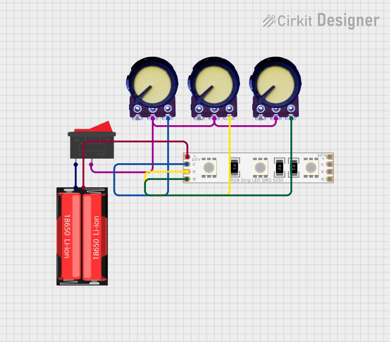
Circuit Documentation
Summary of the Circuit
This circuit appears to be designed to control an RGB LED strip using three potentiometers and a rocker switch. The rocker switch is used to turn the power on or off to the circuit. Each potentiometer is likely intended to control the intensity of one color channel (Red, Green, Blue) of the LED strip. The 18650 Li-Ion battery provides the power source for the circuit.
Component List
Potentiometer
- Description: A variable resistor with three terminals: Ground (GND), Output, and Voltage (VCC).
- Purpose: To adjust the voltage level on its output pin, which is likely used to control the brightness of one color channel on the LED strip.
LED RGB Strip
- Description: A strip of LEDs that can display multiple colors by mixing Red, Green, and Blue light.
- Purpose: To emit colored light, with the color and intensity controlled by the potentiometers.
Rocker Switch
- Description: A simple on/off switch with two terminals.
- Purpose: To allow the user to turn the power to the circuit on or off.
18650 Li-Ion Battery
- Description: A rechargeable battery with a positive and a negative terminal.
- Purpose: To provide a power source for the circuit.
Wiring Details
Potentiometer (All Three Instances)
- GND: Connected to the ground of the circuit.
- Output: Connected to the input of the LED RGB Strip corresponding to one of the color channels (Red, Green, or Blue).
- VCC: Connected to the positive voltage supply (from the battery through the rocker switch).
LED RGB Strip
- Common Connect: Connected to the negative terminal of the 18650 Li-Ion battery.
- Blue Connect: Connected to the output of one of the potentiometers.
- Red Connect: Connected to the output of another potentiometer.
- Green Connect: Connected to the output of the third potentiometer.
Rocker Switch
- Terminal 1: Connected to the positive terminal of the 18650 Li-Ion battery.
- Terminal 2: Connected to the VCC pins of all three potentiometers.
18650 Li-Ion Battery
- Positive: Connected to terminal 1 of the Rocker Switch.
- Negative: Connected to the Common Connect of the LED RGB Strip.
Documented Code
There is no embedded code provided for any microcontrollers in this circuit. If the circuit is intended to be controlled by a microcontroller, the code would be necessary to manage the color mixing and intensity levels based on the potentiometer inputs. However, since no microcontrollers are listed in the parts, and no code is provided, it appears that the circuit is purely analog and does not require programming.