
Arduino Mega 2560-Based Smart Weather Station with Bluetooth Connectivity
View and Edit Project In Cirkit Designer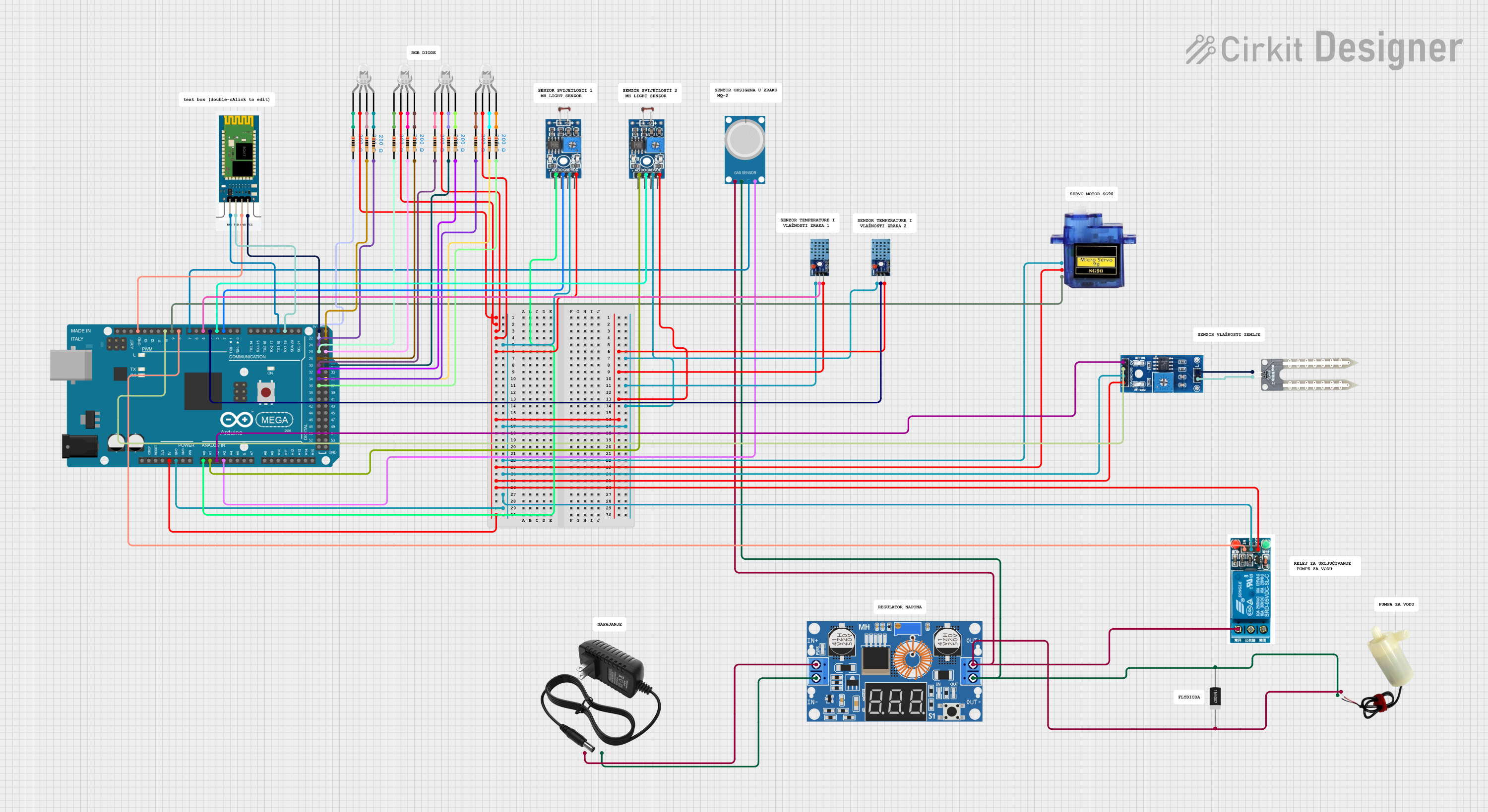
Circuit Documentation
Summary
This document provides a detailed overview of a circuit that includes an Arduino Mega 2560 microcontroller, various sensors (DHT 11, MQ-4, Rain/Snow Sensor, Photosensitive Sensor), a 5V mini water pump, multiple LEDs, a 5V relay, a micro servo, and other components. The circuit is designed to interface with these components to perform various sensing and actuation tasks.
Component List
Arduino Mega 2560
- Description: A microcontroller board based on the ATmega2560.
- Pins: IOREF, RESET, 3V3, 5V, GND, VIN, A0-A15, D0-D53, AREF, SDA, SCL
DHT 11
- Description: A temperature and humidity sensor.
- Pins: VCC, GND, DATA
MQ-4
- Description: A gas sensor for methane (CH4).
- Pins: A0, D0, GND, VCC
Rain/Snow Sensor - Board
- Description: A sensor to detect rain or snow.
- Pins: 1, 2, A0 (Analog), D0 (Digital), GND, VCC (5V)
5V Mini Water Pump
- Description: A small water pump powered by 5V.
- Pins: Positive pin, Negative pin
LED: Four Pin
- Description: A four-pin LED with red, green, and blue cathodes and a common anode.
- Pins: Red cathode, Common anode, Green cathode, Blue cathode
Photosensitive Sensor Module Digital Light Intensity Detection
- Description: A sensor to detect light intensity.
- Pins: Analog Output, Digital Output, Ground, VCC
XL4015 5A DC Buck Step-down
- Description: A DC-DC buck converter.
- Pins: Output +, Output -, Input +, Input -
12V Power Supply
- Description: A power supply providing 12V.
- Pins: +, -
5V Relay
- Description: A relay module that operates at 5V.
- Pins: Normally Open, Common terminal, Normally Closed, In, GND, VCC
Water Sensor
- Description: A sensor to detect water presence.
- Pins: -, +
Micro Servo 9G
- Description: A small servo motor.
- Pins: GND, +5V, PWM
Resistor
- Description: A resistor with a resistance of 200 Ohms.
- Pins: Pin1, Pin2
1N4007 Rectifier Diode
- Description: A general-purpose rectifier diode.
- Pins: Cathode, Anode
HC-06
- Description: A Bluetooth module.
- Pins: RXD, TXD, GND, VCC
Wiring Details
Arduino Mega 2560
- 5V: Connected to VCC of DHT 11, Photosensitive Sensor Module, Micro Servo 9G, Rain/Snow Sensor, 5V Relay, and HC-06.
- GND: Connected to GND of DHT 11, Photosensitive Sensor Module, Micro Servo 9G, Rain/Snow Sensor, 5V Relay, and HC-06.
- A0: Connected to Analog Output of Photosensitive Sensor Module.
- A1: Connected to Analog Output of another Photosensitive Sensor Module.
- A2: Connected to A0 (Analog) of Rain/Snow Sensor.
- A3: Connected to A0 of MQ-4.
- D19/RX1: Connected to TXD of HC-06.
- D18/TX1: Connected to RXD of HC-06.
- D2 PWM: Connected to Digital Output of Photosensitive Sensor Module.
- D3 PWM: Connected to Digital Output of another Photosensitive Sensor Module.
- D4 PWM: Connected to DATA of DHT 11.
- D5 PWM: Connected to DATA of another DHT 11.
- D7 PWM: Connected to D0 of MQ-4.
- D8 PWM: Connected to In of 5V Relay.
- D9 PWM: Connected to PWM of Micro Servo 9G.
- D10 PWM: Connected to D0 (Digital) of Rain/Snow Sensor.
- D22-D36: Connected to pin2 of various resistors.
DHT 11
- VCC: Connected to 5V of Arduino Mega 2560.
- GND: Connected to GND of Arduino Mega 2560.
- DATA: Connected to D4 PWM and D5 PWM of Arduino Mega 2560.
MQ-4
- A0: Connected to A3 of Arduino Mega 2560.
- D0: Connected to D7 PWM of Arduino Mega 2560.
- GND: Connected to Output - of XL4015 5A DC Buck Step-down.
- VCC: Connected to Output + of XL4015 5A DC Buck Step-down.
Rain/Snow Sensor - Board
- VCC (5V): Connected to 5V of Arduino Mega 2560.
- GND: Connected to GND of Arduino Mega 2560.
- A0 (Analog): Connected to A2 of Arduino Mega 2560.
- D0 (Digital): Connected to D10 PWM of Arduino Mega 2560.
- 1: Connected to - of Water Sensor.
- 2: Connected to + of Water Sensor.
5V Mini Water Pump
- Positive pin: Connected to Output + of XL4015 5A DC Buck Step-down.
- Negative pin: Connected to Output - of XL4015 5A DC Buck Step-down.
LED: Four Pin
- Common anode: Connected to 5V of Arduino Mega 2560.
- Red cathode: Connected to pin1 of various resistors.
- Green cathode: Connected to pin1 of various resistors.
- Blue cathode: Connected to pin1 of various resistors.
Photosensitive Sensor Module Digital Light Intensity Detection
- VCC: Connected to 5V of Arduino Mega 2560.
- Ground: Connected to GND of Arduino Mega 2560.
- Analog Output: Connected to A0 and A1 of Arduino Mega 2560.
- Digital Output: Connected to D2 PWM and D3 PWM of Arduino Mega 2560.
XL4015 5A DC Buck Step-down
- Input +: Connected to + of 12V Power Supply.
- Input -: Connected to - of 12V Power Supply.
- Output +: Connected to Positive pin of 5V Mini Water Pump and VCC of MQ-4.
- Output -: Connected to Negative pin of 5V Mini Water Pump and GND of MQ-4.
12V Power Supply
- +: Connected to Input + of XL4015 5A DC Buck Step-down.
- -: Connected to Input - of XL4015 5A DC Buck Step-down.
5V Relay
- VCC: Connected to 5V of Arduino Mega 2560.
- GND: Connected to GND of Arduino Mega 2560.
- In: Connected to D8 PWM of Arduino Mega 2560.
- Normally Open: Connected to Cathode of 1N4007 Rectifier Diode.
Water Sensor
- -: Connected to 1 of Rain/Snow Sensor.
- +: Connected to 2 of Rain/Snow Sensor.
Micro Servo 9G
- GND: Connected to GND of Arduino Mega 2560.
- +5V: Connected to 5V of Arduino Mega 2560.
- PWM: Connected to D9 PWM of Arduino Mega 2560.
Resistor
- Pin1: Connected to various cathodes of LEDs.
- Pin2: Connected to D22-D36 of Arduino Mega 2560.
1N4007 Rectifier Diode
- Cathode: Connected to Normally Open of 5V Relay.
- Anode: Connected to Negative pin of 5V Mini Water Pump.
HC-06
- RXD: Connected to D18/TX1 of Arduino Mega 2560.
- TXD: Connected to D19/RX1 of Arduino Mega 2560.
- GND: Connected to GND of Arduino Mega 2560.
- VCC: Connected to 5V of Arduino Mega 2560.
Documented Code
Arduino Mega 2560 Code
sketch.ino
void setup() {
  // put your setup code here, to run once:

}

void loop() {
  // put your main code here, to run repeatedly:

}
documentation.txt